Table of Contents
Advertisement
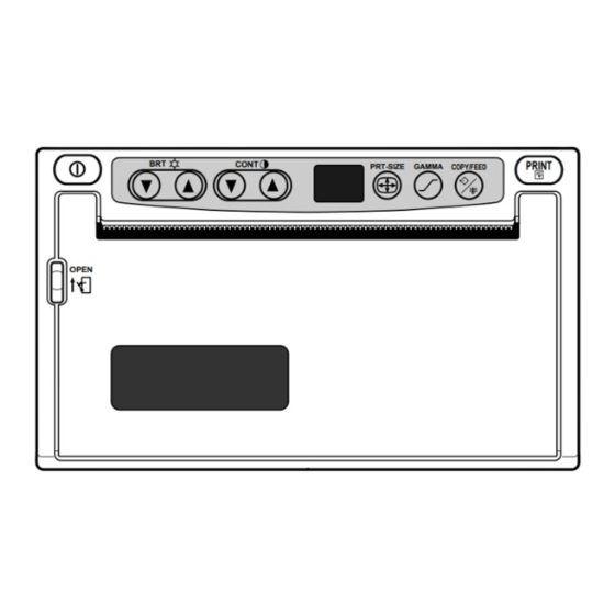
VIDEO COPY PROCESSOR
MODEL
P91W
P91E
OPERATION MANUAL
BRT
CONT
PRT-SIZE
GAMMA
OPEN
VIDEO COPY
This video copy processor complies with the requirements of the EC Directive 89/336/
EEC, 73/23/EEC, 93/42/EEC and 93/68/EEC.
The electro-magnetic susceptibility has been chosen at a level that gains proper
operation in residential areas, on business and light industrial premises and on small-
schale enterprises, inside as well as outside of the buildings. All places of operation
are characterised by their connection to the public low voltage power supply system.
PRINT
COPY/FEED
PROCESSOR
Advertisement
Table of Contents

Related Manuals for Mitsubishi P91W


Summary of Contents for Mitsubishi P91W
- Page 1 VIDEO COPY PROCESSOR MODEL P91W P91E OPERATION MANUAL CONT PRINT PRT-SIZE GAMMA COPY/FEED OPEN VIDEO COPY PROCESSOR This video copy processor complies with the requirements of the EC Directive 89/336/ EEC, 73/23/EEC, 93/42/EEC and 93/68/EEC. The electro-magnetic susceptibility has been chosen at a level that gains proper operation in residential areas, on business and light industrial premises and on small- schale enterprises, inside as well as outside of the buildings.
- Page 2 Use the AC power cord recommended as below and the included composite video cable so as not to interfere with radio and television reception. If you use other cables, it causes interference with radio and television reception. FOR THE MODEL P91W ONLY WARNING: Use the AC power cord according to the recommendations as below, Case 1, 2, 3 and 4;...
- Page 3 CAUTION RISK OF ELECTRIC SHOCK DO NOT OPEN CAUTION: TO REDUCE THE RISK OF ELECTRIC SHOCK, DO NOT REMOVE COVER (OR BACK) NO USER-SERVICEABLE PARTS INSIDE REFER SERVICING TO QUALIFIED SERVICE PERSONNEL. The lightning flash with arrowhead symbol, within an equilateral triangle, is intended to alert the user to the presence of uninsulated "dangerous voltage"...
-
Page 4: Table Of Contents
CONTENTS 1 1 1 1 1 CONTENTS ..............1 2 2 2 2 2 PRECAUTIONS ............2 - 4 3 3 3 3 3 FEATURES AND FUNCTIONS Front Panel ............... 5 Rear Panel ..............6 4 4 4 4 4 INSTALLATION OF PAPER ........7 - 8 5 5 5 5 5 EXAMPLE OF CONNECTION / SETTING OF SWITCHES Composite Video Signal ......... -
Page 5: 2 2 2 2 Precautions
PRECAUTIONS In the interest of safety, please observe the following WARNING : THIS APPARATUS MUST BE EARTHED. precautions: AVERTISSEMENT : CET APPAREIL DOIT ETRE MIS A POWER REQUIREMENT LA TERRE. This Video Copy Processor is designed for operation on This equipment is classified as class 1, type B according to 120/220-240V AC 50/60Hz in U.S.A and Canada, 220- the type of protection against electric shock. - Page 6 Prepare for replacement of the paper. If the Note: remaining paper length is less than 10" (25cm), Mitsubishi brand thermal paper is specially treated printing becomes uneven due to the uneven with an anti-static coating against thermal head paper core surface.
-
Page 7: Technical Description
SAFETY TECHNICAL CHECKS Periods: According to the recommendations of the manufacturer of medical device. Scope: a) Visual check Housing, cables, operator controls, readout device ( displays, LED etc.), labels, accessories, instruction manual. b) Function test Performance check acc. instruction manual, also unity and applicability of set and accessory test. -
Page 8: 3 3 3 3 Features And Functions
FEATURES AND FUNCTIONS Front Panel CONT PRINT PRT-SIZE GAMMA COPY/FEED OPEN Reference Function Name Page Power switch Turns on/off the power. Press these buttons to select brightness Brightness buttons • adjustment mode. Press these buttons to select the contrast Contrast buttons •... -
Page 9: Rear Panel
Rear Panel C D E ADJUST IMP TRAP GAIN IMAGE AFC DIR MEMORY SCAN SAVING PAPER NEGA REV FIELD OVER SUPER H-POSI AFC HIGH OFF POSI NOR FRAME UNDER OFF REMOTE AC LINE VIDEO POTENTIAL EQUALIZATION TERMINAL This is used to equalize the potential of the equipment connected to this unit. -
Page 10: 4 4 4 4 Installation Of Paper
INSTALLATION OF PAPER Paper (High-density paper K65HM) Moisture, fingerprints or dust on the 3 Pull out the paper end. paper surface may cause a noise at printing or deterioration in print quality. Set the paper in the follow- Pull out the first 15- •... - Page 11 When setting the paper, observe the following precautions to prevent paper jam. Do not use defective paper. Do not use the bent or wrinkled paper. Adjust the paper position correctly. When the paper is fed out skewed from the print exit, adjust the paper position so that it is fed out straight.
-
Page 12: Setting Of Switches
EXAMPLE OF CONNECTION / SETTING OF SWITCHES Connecting to various composite video signal equipments such as medical equipment. Composite Video Signal 1 Turn off the power switches of the Video copy processor and Video signal equipment the equipment to be connected. Television 2 Connect the VIDEO input terminal of the Video copy processor to the video output terminal of the connecting... -
Page 13: Medical Video Signal
For the functions of the MODE switch, refer to "MODE SWITCH FUNCTIONS" on page 21 - 23. Medical Video Signal 1 Turn off the power switches of the Video copy processor and the equipment to be connected. 2 Connect the VIDEO input terminal of the Video copy processor to the video output terminal of the connecting equipment. -
Page 14: Printing Procedure
PRINTING Printing Procedure 1 Turn on the power. 3 Cut the printed paper. • Press the • Cut the printed “POWER” paper with the switch to turn cutter by on the power. tearing off the paper in the upper right direction. -
Page 15: Use Of Remote Control
Use of Remote Control Connect the wired remote control to Rear panel the remote control terminal on the ADJUST IMP TRAP GAIN IMAGE AFC DIR MEMORY SCAN SAVING PAPER rear panel. NEGA REV FIELD OVER SUPER H-POSI AFC HIGH OFF POSI NOR FRAME UNDER OFF REMOTE... -
Page 16: 7 7 7 7 Adjustment Of Print Picture
ADJUSTMENT OF PRINT PICTURE Adjustment of Brightness/Contrast You can adjust brightness and contrast of print while observing the monitor screen. Control panel CONT PRT-SIZE GAMMA COPY/FEED To adjust pictures, use the bright buttons "}" and "{" of BRT " ", the contrast buttons •... -
Page 17: Abc Mode (Automatic Brightness Control)
2 Store the set value. PRINT A value is stored by pressing "PRINT" CONT PRINT PRT-SIZE GAMMA COPY/FEED button. OPEN A stored value will not be lost even if the power is turned off. ABC mode (Automatic Brightness Control) ABC mode can be set to adjust the brightness of the print picture. -
Page 18: Selection Of Gamma ( ) Curve
Releasing ABC mode Hold down the print size button " " for approx. 3 seconds. A tone is given, LED display changes from and ABC mode is released. Selection of Gamma ( ) Curve You can select -curve by pressing the gamma button " ". -
Page 19: Selection Of Print Size
Selection of Print Size You can select print size by pressing the print-size button " ". Each time the button is pressed, CONT PRT-SIZE GAMMA COPY/FEED the indicator and print size is switched as follows. After a print size has been selected, press any other button to store the print size. -
Page 20: 8 8 8 8 Special Function
SPECIAL FUNCTION Locking the settings You can lock the setting of each button on the front panel (BRT, CONT, PRT-SIZE, GAMMA) . Locking the setting (e.g. brightness) 1 Turn on the power. 2 Lock the setting of the brightness (BRT) Press the "POWER"... -
Page 21: Printing The Set Conditions
Printing the set conditions You can print the set conditions of BRT, CONT and GAMMA under the image. 1 Turn on the power. 3 Set to the stand-by status. While holding down the "}" of BRT • Press the "POWER" switch to turn on •... -
Page 22: 9 9 9 9 Error Display
ERROR DISPLAY When an error in operation occurs it is warned by an audible alarm and a visible error display in the LED indicator. Cause/Error display Symptom/ Remedy 1 No paper [Symptom] • When the paper runs out or the paper is not installed, printing becomes impossible and alarm tone is given. -
Page 23: Error Display
Cause/Error display Symptom/ Remedy 4 Door error [Symptom] • When the door opens, an alarm tone is given. [Remedy] Close the door. Symptom/ Remedy Cause/Error display [Symptom] 5 Gear lock error • When the thermal head does not automatically go up after printing, an alarm tone is given. -
Page 24: A A A A A Mode Switch Functions
MODE SWITCH FUNCTIONS IMP TRAP GAIN IMAGE AFC DIR MEMORY SCAN SAVING PAPER NEGA REV FIELD OVER SUPER HIGH OFF POSI NOR FRAME UNDER OFF REMOTE MODE SWITCH Functions (DIP switch) 1 IMP Usually set to "75 ". (IMPEDANCE) Set to "HIGH" when making branch connection of a monitor 75 /HIGH or other units to the VIDEO IN connector. - Page 25 MODE SWITCH Functions (DIP switch) 5 AFC Usually set to "OFF". ON/OFF Set to "ON" when connecting equipment with a poor signal. Picture quality will be improved. 6 DIR NOR (NORMAL): A picture is printed in the same direction as (DIRECTION) the display.
- Page 26 MODE SWITCH Functions (DIP switch) 9 SAVING Set this switch to select the margin size. (PAPER SAVING) ON: Printed with narrow margin. ON/OFF OFF: Printed with normal margin. Narrow Normal Narrow Margin Normal Margin A PAPER Set this switch as follows to suit the thermal paper used: SUPER/HD Position Thermal paper...
-
Page 27: B B B B B Status And Modes
STATUS AND MODES LED display Contents of right Video Set state/Mode Point and side LED display output Left right Through Power off Power off Except small size Through Small size Through Stand-by for 1st image Small size Through for 2nd image Through Print state Print state... -
Page 28: C C C C C Use Of Cleaning Paper
USE OF CLEANING PAPER When the thermal head is dirty with dust and perspiration, etc., white spots or stripes may appear on the print. In this case, clean the thermal head in the following procedure BY USING THE SUPPLIED CLEANING PAPER. 1 Turn on the power. -
Page 29: D D D D D Maintenance
MAINTENANCE Turn off the power for maintenance. Maintenance of Main Unit Wipe off stains of the front panel with a soft cloth. When the panel is heavily stained, wipe off with the cloth moistened with neutral cleanser diluted by water and finish with a dry cloth. -
Page 30: E E E E E Specifications
SERVICE INFORMATION Before requesting service please review this operation manual to correct minor complaints. If you are unable to correct the problem, consult your MITSUBISHI Dealer or MITSUBISHI Service Department. DO NOT ADJUST ANY CONTROLS NOT DESCRIBED IN THIS OPERATION MANUAL. - Page 31 Polígono Industrial "Can Magí", Calle Joan Bucallà 2-4, Apartado de Correos 420, 08190 Sant Cugat del Vallês, Barcelona, Spaín Phone 93.5653154 FAX 93.5894388 Manufactured by Mitsubishi Electric Corporation 1 Zusho Baba, Nagaokakyo-City, Kyoto Japan Made from recycled paper 871C957D8 PRINTED IN JAPAN...
Need help?
Do you have a question about the P91W and is the answer not in the manual?
Questions and answers