
Related Manuals for Henry Schein COLPOSCOPE I


Summary of Contents for Henry Schein COLPOSCOPE I
- Page 1 HENRY SCHEIN COLPOSCOPE I USER’S MANUAL (570-0144 and 570-0145) Distributed by (in US only) HENRY SCHEIN INC. 135 DURYEA ROAD MELVILLE, NY 11747 USA MC-55-248-001 REV 4/2016 yyyy-mm-dd...
- Page 2 570-0144 and 570-0145 Please read this manual carefully before operating your Colposcope. We thank you for choosing the Henry Schein® Articulating Arm Colposcope. This precisely built, durable Colposcope will give you years of service. If ever you require an additional accessory or spare part, please contact your Henry Schein®...
- Page 3 Repairs may only be carried out by trained service technicians, or by authorized personnel. Contact Henry Schein® for details. The Henry Schein® Articulating Arm Colposcope is an optical instrument for use as a diagnostic aide. The system includes three main components: 1.
-
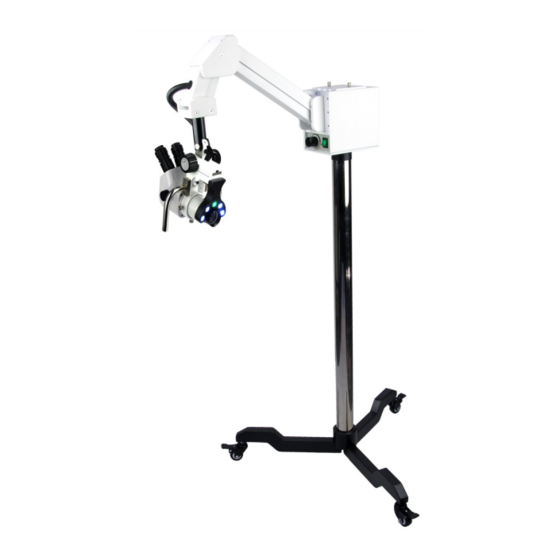
Page 4: Suspension Arm Installation
Overall height: 63″ (1600mm) Overall weight: 77.1bs/35kgs (stand 69.1bs/31.5kgs, head 8.1bs/3.5kgs) Center of column to the end of leg: 16-1/2″ (420mm) The horizontal distance from the center of column to the mount of the zoom body is 30″... - Page 5 Fig. 4 Zoom Head Installation 1. Insert the Colposcope head into the focusing mount (Fig. 5). 2. Tighten the locking screws (Fig. 5). 3. Insert the eyepieces into the eyepiece tubes of the binocular or trinocular head (Fig. 6). 4. Screw the objective lens clockwise onto the bottom of the Colposcope head (Fig. 7). Fig.
- Page 6 Fig. 8 To tighten left / right motion Find the set screws labeled “B” (Fig. 9) and follow the same instructions as above in tightening up and down motion. Fig. 9...
-
Page 7: Fuse Replacement
Magnification and Power (magnification) Setting Zoom Setting Eyepiece: WF20X Objective lens: 0.3X Working distance: 298mm Mag. power Field of view 0.67X 3.9X 58.5 38.3 1.5X 25.6 19.2 2.5X 15.3 12.8 3.5X 4.5X Total magnification = eyepiece × head power on power knob × objective lens (Fig. 10) Fig. -
Page 8: Operation
Each leg is equipped with a locking caster/wheel. If desired, they may be individually locked by pushing down on the lock lever; to unlock, lift up the lever. (Fig. 11A, 11B) Fig. 11B Fig. Operation Turn the On/Off switch to “ON”; adjust the light intensity by turning the adjustment knob. - Page 9 Use the handles and focusing knob to focus on the surface of the cervix (Fig. 13). Fig. 13 The tension of the focusing knobs has been pre-set by factory technicians. To increase the focusing tension, hold the left knob with your left hand; use your right hand to turn the right knob clockwise.
- Page 10 Focusing Rotate the zoom knobs to the highest power 4.5x (Fig. 15). Set the diopters on both eyepiece tubes to “0” (Fig.16). Then use the focusing knobs to focus on the cervix. Fig. 16 Fig. 15 Rotate the zoom knobs to get the lowest power 0.67x (Fig. 17). DO NOT TOUCH the focusing knob on the focusing mount.
Need help?
Do you have a question about the COLPOSCOPE I and is the answer not in the manual?
Questions and answers