Table of Contents
Advertisement
Quick Links
SPX FLOW US, LLC
5885 11th Street
Rockford, IL 61109-3699 USA
powerteam.com
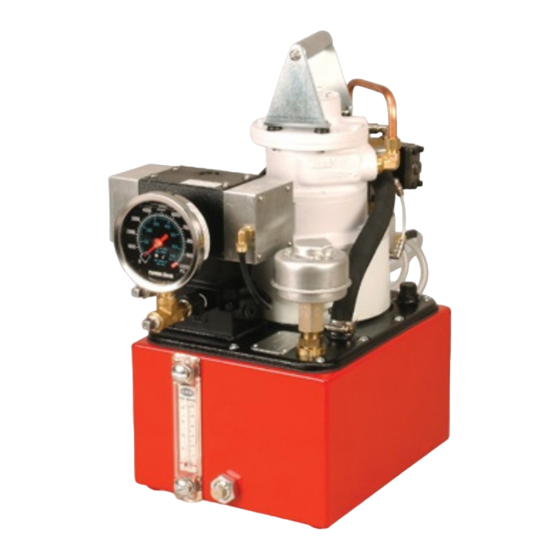
TWO-STAGE AIR HYDRAULIC PUMP
© SPX FLOW, Inc.
Tech Services: (800) 477-8326
Fax: (800) 765-8326
Order Entry: (800) 541-1418
Fax: (800) 288-7031
Max. Capacity: 10,000 PSI
MODEL SHOWN FOR RWP55
Operating Instructions For:
RWP55
RWP55-4
Form No. 102977
Rev. 2
Jun. 02, 2022
Advertisement
Table of Contents

Subscribe to Our Youtube Channel
Related Manuals for Power Team SPXFLOW RWP55


Summary of Contents for Power Team SPXFLOW RWP55
- Page 1 Operating Instructions For: RWP55 RWP55-4 Tech Services: (800) 477-8326 SPX FLOW US, LLC Fax: (800) 765-8326 5885 11th Street Order Entry: (800) 541-1418 Rockford, IL 61109-3699 USA Fax: (800) 288-7031 powerteam.com TWO-STAGE AIR HYDRAULIC PUMP Max. Capacity: 10,000 PSI MODEL SHOWN FOR RWP55 Form No.
-
Page 2: Table Of Contents
5� Draining And Flushing The Reservoir ��������������������������������������������������������������������������������������������������� 7 6� Adding oil to the Reservoir �������������������������������������������������������������������������������������������������������������������� 7 TROUBLESHOOTING GUIDE ���������������������������������������������������������������������������������������������������������������������������� 9 POWER TEAM FACILITIES AND CONTACT �������������������������������������������������������������������������������������������������� 12 ATEX DECLARATION OF CONFORMITY ������������������������������������������������������������������������������������������������������� 13 EC DECLARATION OF CONFORMITY ����������������������������������������������������������������������������������������������������������� 14 UKCA DECLARATION OF CONFORMITY ������������������������������������������������������������������������������������������������������ 15 Form No. -
Page 3: Safety Symbols And Definitions
SAFETY SYMBOLS AND DEFINITIONS Safety symbols are used to identify any action or lack of action that can cause personal injury. Your reading and understanding of these safety symbols is very important. : Danger is used only when your action or lack of action will cause serious human injury or death : Warning is used to describe any action or lack of action where a serious injury can WARNING... - Page 4 Safety Precautions Continued Pump • Do not exceed the PSI hydraulic pressure rating noted on the pump nameplate or tamper with the internal high pressure relief valve. Creating pressure beyond rated capacities can result in personal injury. • Before replenishing the oil level, retract the system to prevent overfilling the pump reservoir. An overfill can cause personal injury due to excess reservoir pressure created when the cylinders are retracted.
-
Page 5: Hydraulic Pump Set-Up Procedure
TWO-STAGE AIR HYDRAULIC PUMP (Max. Capacity: 10,000 PSI) NOTE: • Carefully inspect the pump upon arrival. The carrier, not the manufacturer, is responsible for any damage resulting from shipment. • Read and carefully follow these instructions. Most problems with new equipment are caused by Improper operation or installation. -
Page 6: Set-Up And Operation
SET-UP AND OPERATION 1. Filling the Reservoir NOTE : The pump has been shipped without oil in the reservoir. High-grade hydraulic oil has been shipped with the pump in a separate container. If additional oil is required, use a high-grade, approved hydraulic oil. -
Page 7: 4� Adjusting The Pressure Regulating Valve
Set-Up and Operation Continued 4. Adjusting The Pressure Regulating Valve NOTE: For easy adjustment of the pressure regulating valve, always adjust the pressure by increasing to the desired pressure setting. A� Loosen the wing nut on the pressure regulating valve, and turn the knob out a few turns in a counterclockwise direction�... -
Page 8: 4� Maintenance Cleaning
Preventive Maintenance Continued 4. Maintenance Cleaning A� Keep the pump’s outer surface as free from dirt as possible� B� Seal all unused couplers with thread protectors� C� Keep all hose connections free of dirt and grime� D� The breather-hole in the filler cap must be clean and unobstructed at all times. E�... - Page 9 Preventive Maintenance Continued REASSEMBLY SPECIFICATIONS HIGH PRESSURE PUMP ASSEMBLY BOLT TIGHTENING SEQUENCE NEEDLE BEARING INSTALLATION SPECIFICATIONS Form No. 102977 © SPX FLOW, Inc. Rev. 2 Jun. 02, 2022...
-
Page 10: Troubleshooting Guide
TROUBLESHOOTING GUIDE WARNING • To help prevent personal injury, any repair work or troubleshooting must be done by qualified personnel familiar with this equipment. • Use the proper gauges and equipment when troubleshooting. NOTE: • It is often best to check for leaks by using a hand pump and applying pressure to the suspect area without the motor running. - Page 11 Troubleshooting Guide Continued PROBLEM CAUSE SOLUTION Pump is not delivering oil or 11� Sheared drive shaft key(s) 11� Replace� delivers only enough oil to 12� Motor rotating in working 12. Air motor: Air line connected into wrong advance cylinder(s) partially direction�...
- Page 12 Troubleshooting Guide Continued PROBLEM CAUSE SOLUTION Pump will not build full 6� Inspect the pump for 6� Same procedure as above, but look pressure (continued). internal leakage� Check for leaks around the entire inner high pressure pump inlet or mechanism� If there are no visible leaks, outlet ball checks�...
-
Page 13: Power Team Facilities And Contact
POWER TEAM FACILITIES AND CONTACT Rockford, Illinois USA European Headquarters Asia Pacific Headquarters Customer Service/Order Entry Tel: +31 45 567 8877 Tel: +65 6265 3343 Tel: +1 800 541 1418 Fax: +31 45 567 8878 Fax: +65 6265 6646 Fax: +1 800 288 7031 infoeurope@powerteam.com... -
Page 14: Atex Declaration Of Conformity
English Original DECLARATION OF CONFORMITY We declare under our sole responsibility that the Air-driven Hydraulic Pump models RWP55, RWP55-4, RWP55-4-BS, RWP55-4-BS-R, RWP55-4-BS-RH, RWP55-4-BS-RW, RWP55-4-BS-RWH, RWP55-DUAL, RWP55-4-Q5495, RWP55-BS, RWP55-BS-R, RWP55-BS-RH, RWP55-BS-RW, RWP55-BS-RWH, RWP55-IBT-AIR, RWP55-Q10757, RWP55-Q4421, RWP55-Q5495, RWP55-Q6254, RWP55-Q9856, RWP55-TL, RWP55-PAT TORC-UP API000P HYTORC-AIR series JET-AIR series to which this declaration relates are in conformity with the following :... -
Page 15: Ec Declaration Of Conformity
English Original EC DECLARATION OF CONFORMITY We declare under our sole responsibility that our Air Torque Wrench Pump Model: * RWP55 - series, * Torc-Up AP 1000-P, *HYTORC-AIR – series, * JET-AIR - series to which this declaration relates are in conformity with the following: EN, EN-ISO, ISO standards Title Per the provisions of the Machinery Safety Directive... -
Page 16: Ukca Declaration Of Conformity
English Original UKCA DECLARATION OF CONFORMITY We declare under our sole responsibility that our Air-driven Torque Wrench Pump Model: * RWP55 - series, * Torc-Up AP 1000-P, * HYTORC-AIR – series, * JET-AIR - series to which this declaration relates are in conformity with the following: Legislation &...
Need help?
Do you have a question about the SPXFLOW RWP55 and is the answer not in the manual?
Questions and answers