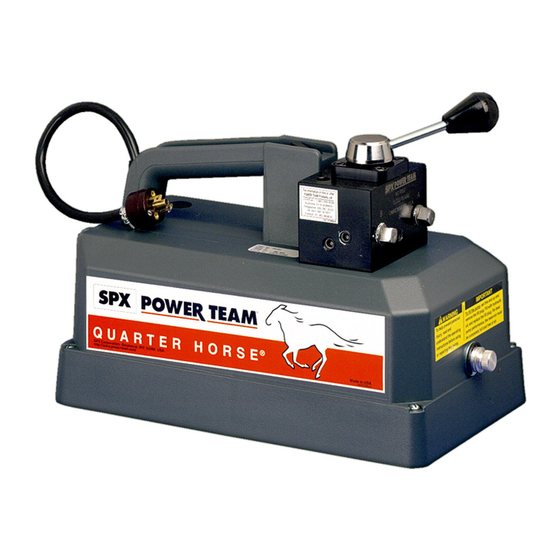
Power Team PE10 Series Operating Instructions Manual

Power Team PE10 Series Operating Instructions Manual

Hydraulic pump

Advertisement

Operating Instructions for:
PE10 Series
Electric-Powered
10 Series
Hydraulic Pump
Form No. 1000573
Rev. 0 February 8, 2012
© SPX

Advertisement

Table of Contents
loading
Need help?

Need help?

Do you have a question about the PE10 Series and is the answer not in the manual?

Questions and answers

Summary of Contents for Power Team PE10 Series

  • Page 1 Operating Instructions for: PE10 Series Electric-Powered 10 Series Hydraulic Pump Form No. 1000573 Rev. 0 February 8, 2012 © SPX...
  • Page 2 Form No. 1000573 Rev. 0 February 8, 2012 © SPX...
  • Page 3: Table Of Contents

    Power Team Facilities ........
  • Page 4: Description

    Description The 10 series hydraulic pumps are designed to have a maximum of 690 bar (10,000 psi) at a flow rate of 164 cc/min (10 cu. in/min). A pump can be valved for use with either single- or double-acting cylinders. All pumps come fully assembled, less fluid, and ready for work. PE10-Series Electric / Hydraulic Pumps Electric Driven Motor Motors are available in 0.186 kW (1/4 HP) in three voltages: 110/115VAC, 220/230 VAC, and 12 VDC.
  • Page 5: Control Valves

    Control Valves Max. Capacity: 690 bar (10,000 psi) Valve Function Use with Valve No. Cylinder Type Single-acting 9561 2-way/auto dump, Advance Return advance return (auto) Pump “ON” Pump “OFF” Hold Position Return Position Diagrams PE102 PE102-220 PR102 From Pump Tank Valve Function Use with Valve No.
  • Page 6: Safety Symbols And Definitions

    Only the user can decide the suitability of this product in these conditions or extreme environments. Power Team will supply information necessary to help make these decisions. Consult your nearest Power Team facility.
  • Page 7 Safety Precautions continued • Do not connect pump to hydraulic system powered by another pump. Electric-Driven Motor WARNING: • Electrical work must be performed and tested by a qualified electrician per local directives and standards. • Disconnect the pump from the power supply and relieve pressure before removing the motor case cover or performing maintenance or repair.
  • Page 8 Safety Precautions continued • Avoid straight line tubing connections in short runs. Straight line runs do not provide for expansion and contraction due to pressure and/or temperature changes. • Eliminate stress in the tube lines. Long tubing runs should be supported by brackets or clips.
  • Page 9 Safety Precautions continued IMPORTANT • Keep the cylinder clean at all times. • While at a job site, when the cylinder is not in use, keep the piston rod fully retracted and upside down. • Always use protective covers on disconnected quick couplers. •...
  • Page 10: Initial Setup

    Most pumps are shipped without hydraulic fluid in the reservoir or bladder. Hydraulic fluid may have been shipped in a separate container, but if hydraulic fluid is needed, use only approved Power Team hydraulic fluid rated at 47 cSt @ 38°C (215 SUS @ 100°F).
  • Page 11 With no load on the system and the pump vented and positioned higher than the hydraulic device, cycle the system several times. Check the reservoir fluid level and fill to proper level with Power Team hydraulic fluid as necessary. If there is a problem contact Power Team.
  • Page 12 Initial Setup continued IMPORTANT: Some spring return cylinders have a cavity in the rod which forms an air pocket. This type of cylinder should be bled when positioned upside down or lying on its side with the port facing upward. Hydraulic Pressure Gauge (optional) Automatic Dump Valve To monitor line pressure when using an automatic dump valve, a T-adapter is used between the valve...
  • Page 13 Initial Setup continued 2. See Figure 5. Install sealant tape or non hardening sealer to a 45 degree elbow (PN 9678). Install the elbow as shown. 3. Install sealant tape or non hardening sealer to the gauge. Figure 5. Elbow Installation 4.
  • Page 14: Operating Instructions

    Bleeding Air from the System 1. Cycle the hydraulic system until operation is smooth and consistent. 2. Check the pump reservoir level. Add Power Team hydraulic fluid as needed. Motor Control Operation 1. If necessary, connect the power cord to an appropriate power source.
  • Page 15: Performance Specifications

    Performance Specifications The information in the following charts can be used as a basis to determine if the system is performing as expected during operation. Amp Draw at Amp Draw at dBa at Idle Air Supply Pump 690 bar (10,000 690 bar (10,000 and 690 bar Req'd bar (psi)
  • Page 16: General Maintenance

    • Keep hose connections free of debris. Equipment attached to a cylinder must be kept clean. • Keep the breather-hole in the filler cap clean and unobstructed. • Use only Power Team hydraulic fluid. Replace hydraulic fluid as recommended, or sooner if the fluid becomes contaminated. Never exceed 300 hours of use between fluid changes.
  • Page 17 3. Clean the entire area around the filler plug. 4. Remove the filler plug, and install a clean funnel with a filter. 5. Use only Power Team hydraulic fluid 47 cSt @ 38°C (215 SUS @ 100°F). Sound Reduction - Electrically Powered Motor The electrically powered hydraulic pump operates in the 90-95 dBA range.
  • Page 18: Troubleshooting Guide

    Notes: • For a detailed parts list or to locate a Power Team Authorized Hydraulic Service Center, contact your nearest Power Team facility. • Plug the outlet ports of the pump when checking for leakage to determine if the leakage is in the pump, in the cylinder, or in the tool.
  • Page 19 Pump delivers excess fluid 1. Faulty pressure gauge. 1. Replace gauge. pressure. 2. Relief valve set incorrectly. 2. Contact a Power Team Service Center. Pump is not delivering 1. Fluid level too low. 1. Add fluid, refer to filling the pump fluid, or delivers only reservoir in Initial Setup section.
  • Page 20 3. Attached component sticking or 3. Refer to manufacture's binding. information for attached component. 4. Malfunctioning valve. 4. Verify connections. Contact authorized Power Team Service Center. Form No. 1000573 Rev. 0 February 8, 2012 © SPX...
  • Page 21: Power Team Facilities

    Power Team Facilities UNITED ST ATES CHINA EUROPE C E R T I F I E D SPX Hydraulic Technologies No. 1568 Hua Shan Road Albert Thijsstraat 12 International Park Center 6471 WX Eygelshoven 5885 11th Street The Netherlands Shanghai 200052, China...
  • Page 23 Form No. 102808 Operating Instructions for: PE102 PE102A-220-FE PE104-220 PE102A PE102A-AERO PR102 PE102-28-DC PE102A-COR PR102-AMP PE102-28-220DC PE102A-EMP P2102-ANCHOR PE102-28-FSC PE102A-ETT PR102A PE102-220 PE102AR PR102A-FE PE102-ANCHOR PE102AR-220 PR104 PE102A-220 PE104 PR102-HURST-EPR ELECTRIC HYDRAULIC PUMP Max. Capacity: 10,000 PSI NOTE: • Inspect the pump upon arrival. •...
  • Page 24 Operating Instructions, Form No. 102808, Back sheet 1 of 3 Safety Precautions (Continued) Pump • Do not exceed the PSI hydraulic pressure rating noted on the pump name plate or tamper with the internal high pressure relief valve. Creating pressure beyond rated capacities may result in personal injury. •...
  • Page 25 Operating Instructions Form No. 102808 Valve Operation 2-Position, 2-Way Manual Valves used with Single-acting Cylinders 1. To build pressure, turn the valve control handle counterclockwise (CCW). 2. Start the pump by pressing the motor control ON/OFF switch. NOTE: Oil advances the cylinder when the unit is activated.
  • Page 26 (or vertical) position, the oil level should be at the top of the filler hole. 2. When adding oil, use Power Team approved, high-grade hydraulic oil (215 SSU @ 100°F). Retract the cylinders and disconnect the power supply. Clean the area around the filler plug, remove the plug, and insert a clean funnel with filter.
  • Page 27 Operating Instructions Form No. 102808 ELECTRICAL SCHEMATIC 115/230 V., 50/60 Hz, SINGLE PHASE 6.25A Transformer Connections: CONTROL CIRCUIT For 115 VAC H1 & H3 to L1 H2 & H4 to L2 For 230 VAC H1 to L1 H2 to H3 H4 to L2 REMOTE Sheet No.
  • Page 28 Operating Instructions, Form No. 102808, Back sheet 3 of 3 ELECTRICAL SCHEMATIC 12 VDC (CCW ROTATION FROM LEAD END) L2 ( - ) L1 ( + ) OPTIONAL REMOTE WORLD HEADQUARTERS ASIA PACIFIC CUSTOMER EUROPEAN CUSTOMER THE AMERICAS CUSTOMER SERVICE CENTER SERVICE CENTER SERVICE CENTER 7 GUL CIRCLE...

Table of Contents