Table of Contents
Advertisement
Quick Links
LEC-GMJ2#-TF222-184EN
ORIGINAL INSTRUCTIONS
Instruction Manual
Gateway (GW) unit
CC-Link compatible
Series LEC-GMJ2*
The intended use of the gateway unit is to connect to step motor
controllers which control the movement of an electric actuator, while
connected to the CC-Link network.
1 Safety Instructions
These safety instructions are intended to prevent hazardous situations
and/or equipment damage. These instructions indicate the level of
potential hazard with the labels of "Caution," "Warning" or "Danger."
They are all important notes for safety and must be followed in addition
to International Standards (ISO/IEC)
*1)
, and other safety regulations.
IEC 60204-1: Safety of machinery - Electrical equipment of machines.
(Part 1: General requirements)
ISO 10218-1: Robots and robotic devices - Safety requirements for
industrial robots - Part 1: Robots.
• Refer to product catalogue, Operation Manual and Handling
Precautions for SMC Products for additional information.
• Keep this manual in a safe place for future reference.
Caution indicates a hazard with a low level of risk which, if
Caution
not avoided, could result in minor or moderate injury.
Warning indicates a hazard with a medium level of risk
Warning
which, if not avoided, could result in death or serious injury.
Danger indicates a hazard with a high level of risk which, if
Danger
not avoided, will result in death or serious injury.
Warning
• Always ensure compliance with relevant safety laws and
standards.
• All work must be carried out in a safe manner by a qualified person in
compliance with applicable national regulations.
Refer to the operation manual or catalogue on the SMC website (URL:
https://www.smcworld.com) for further Safety Instructions.
2 Specifications
2.1 General specifications
Item
Specifications
Rated voltage
24 VDC ±10%
200 mA max. (with no teaching box)
Current consumption
300 mA max. (with teaching box)
Applicable controller
Electric actuator controller (LECP6, LECA6)
Connected product
12 pcs. maximum
Cooling method
Natural air-cooling
Operating
0°C to 40°C (no freezing)
temperature
Storage temperature
-10
o
C to 60
o
C (no freezing)
Operating humidity
90% RH or less (no condensation)
2
Vibration resistance
4.9 m/s
Enclosure rating
IP20
50 MΩ (500 VDC)
Insulation resistance
between housing (radiation fin) and FG
200 g (Direct mounting type)
Weight
220 g (DIN rail mounting type)
2 Specifications (continued)
2.2 CC-Link specifications
Item
Specifications
Fieldbus
CC-Link version 2.0
Station type
Remote device station
4 stations extended cyclic 8 times
Occupied number of stations
(Input 896 points 108 word /
Output 896 points 108 word)
156 kbps / 625 kbps / 2.5 Mbps /
Communication speed
5 Mbps / 10 Mbps
Communication method
Broadcast Polling System
Synchronization system
Frame synchronous communication
Encoding method
NRZI
Transmission system
Bus system (EIA RS485 compliant)
Communication format
HDLC compliant
16
12
5
Error control system
CRC (X
+X
+X
+1)
Applicable communication
CC-Link cable
cable
Comms.
156k
625k
2.5M
5M
Speed (bps)
Maximum
cable length
Total cable
1200
900
400
160
length (m)
2.3 Controller I/F communication specifications
Item
Specifications
Serial
RS485 (Modbus protocol compatible)
communication
Communication
115.2 kbps or 230.4 kbps (select 115.2 kbps
speed
when the teaching box is connected)
The cable for the teaching box (3 m) and the
electric actuator controller (3 m x 12) = 39 m.
This is the maximum allowable cable length.
Cable length
・・・
3m
3m
3m
3m
Warning
Special products (-X) might have specifications different from those
shown in this section. Contact SMC for specific drawings.
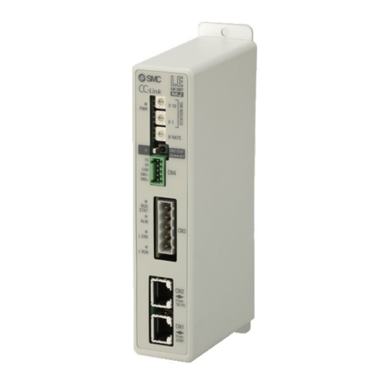
3 Name and function of parts
No.
Name
Description
1
LED display
LED to indicate the gateway status.
STATION NO. address
2
Switch to set address X1 and X10.
switch
B RATE communication
Switch to set the communication
3
speed switch
speed to the controller IF.
To enable communication with
CN2 SW communication
4
equipment on CN2 and disable
switch
communication with controller IF.
5
CN4 power connector
Connection for power supply / EMG.
6
CN3 bus connector
Connection for CC-Link.
Connection for teaching box or PC
7
CN2 TB / PC connector
with controller setting software.
8
CN1 CONT connector
Connection for controller IF.
4 Installation
4.1 Installation
Warning
• Do not install the product unless the safety instructions have been read
and understood.
4.2 Mounting
• The gateway can be direct mounted (model LEC-GMJ2) using 2 x M4
screws or mounted on a DIN rail (model LEC-GMJ2D).
• When using DIN rail mounting, hook the gateway on the DIN rail and
press the lever in the direction of Arrow A to lock it.
Direct mounting
DIN rail mounting
Screw direction
10M
100
Screw direction
4.3 Environment
Warning
• Do not use in an environment where corrosive gases, chemicals, salt
water or steam are present.
• Do not use in an explosive atmosphere.
• Do not expose to direct sunlight. Use a suitable protective cover.
• Do not install in a location subject to vibration or impact in excess of
3m
the product's specifications.
• Do not mount in a location exposed to radiant heat that would result in
temperatures in excess of the product's specifications.
• Avoid mounting the gateway near a vibration source, such as a large
electromagnetic contactor or circuit breaker on the same panel.
• Do not use in an environment with strong magnetic fields present.
5 Wiring
5.1 Wiring
Caution
• Do not perform wiring while the power is on.
• Confirm proper insulation of wiring.
• Do not route wires and cables together with power or high voltage
cables.
• Keep wiring as short as possible to prevent interference from
electromagnetic noise and surge voltage.
• Do not use an inrush current limited type of power supply for the
gateway.
• Do not connect multiple wires to one connector terminal.
5.2 Power Supply Connector (CN4)
Wire the power supply cable to the power supply plug connector, then
insert it into connector CN4 on the gateway.
• Use special screwdriver (Phoenix Contact
No. SZS0.4×2.0) to open / close the lever
and insert the wire into the connector
terminal.
• Applicable wire size:
Wire entry
2
20 AWG (0.5 mm
).
No.
Terminal
5
FG
4
0V
3
24V
2
EMG-
1
EMG+
5 Wiring (continued)
5.3 Ground connection
• Connect a ground wire to the FG terminal (pin 5) on the power supply
connector (CN4).
FG terminal
The M4 screw, cable with crimped terminal and shakeproof washer must
be prepared by the user.
The gateway must be connected to Ground to shield it from electrical
noise.
• A dedicated Ground connection must be used. Grounding should be
DIN rail
to a D-class ground specification (resistance of 100 Ω maximum).
• The cross-sectional area of the ground cable shall be 2 mm
• The Grounding point should be as near as possible to the gateway.
Keep the grounding cable as short as possible.
Gateway
Other
device
unit
Recommended FG
5.4 Bus connector (CN3)
No.
1
1
2
3
2
4
3
5
4
5
5.5 Terminating resistor
• Connect the terminating resistor to both ends of the CC-Link main
communication line.
• For the CC-Link system, the terminating resistor value depends upon
the type of cable used.
Type of cable
Communication cable for CC-Link
CC-Link dedicated high-performance
cable
Lever
Description
FG terminal
Power supply -
Power supply +
EMG output -
EMG output +
Lever
Caution
2
minimum.
Gateway
Other
unit
device
Not Recommended
Terminal
Description
CC-Link communication
DA
line A
CC-Link communication
DB
line B
DG
CC-Link ground
SLD
CC-Link shield
FG
Frame ground
Caution
Resistance
110 ohms, 1/2 W
130 ohms, 1/2 W
Page 1 of 2
Advertisement
Table of Contents

Related Manuals for SMC Networks LEC-GMJ2 Series


Summary of Contents for SMC Networks LEC-GMJ2 Series
- Page 1 LEC-GMJ2#-TF222-184EN 2 Specifications (continued) 4 Installation 5 Wiring (continued) ORIGINAL INSTRUCTIONS 2.2 CC-Link specifications 4.1 Installation 5.3 Ground connection • Connect a ground wire to the FG terminal (pin 5) on the power supply Warning Item Specifications connector (CN4). Instruction Manual Fieldbus CC-Link version 2.0 •...
- Page 2 LEC-GMJ2#-TF222-184EN 6 Wiring Diagram 7 How to Order The system structure for using the Gateway unit is shown below. Refer to the catalogue on the SMC website (URL: https://www.smcworld.com) for the How to Order information. ●Teaching box 8 Outline Dimensions (mm) LEC-T1-3#G# CC-Link Terminating...
Need help?
Do you have a question about the LEC-GMJ2 Series and is the answer not in the manual?
Questions and answers