H3C UniServer B5800 G3 User Manual
Blade server
Hide thumbs
Also See for UniServer B5800 G3:
- Operating system installation manual (141 pages) ,
- User manual (401 pages)

Subscribe to Our Youtube Channel
Related Manuals for H3C UniServer B5800 G3


Summary of Contents for H3C UniServer B5800 G3
- Page 1 H3C UniServer B5800 G3 Blade Server User Guide New H3C Technologies Co., Ltd. http://www.h3c.com Document version: 6W100-20230213...
- Page 2 The information in this document is subject to change without notice. All contents in this document, including statements, information, and recommendations, are believed to be accurate, but they are presented without warranty of any kind, express or implied. H3C shall not be liable for technical or editorial errors or omissions contained herein.
- Page 3 Preface This preface includes the following topics about the documentation: • Audience. • Conventions. • Documentation feedback. Audience This documentation is intended for: • Network planners. • Field technical support and servicing engineers. • Server administrators working with the Server. Conventions The following information describes the conventions used in the documentation.
- Page 4 Symbols Convention Description An alert that calls attention to important information that if not understood or followed WARNING! can result in personal injury. An alert that calls attention to important information that if not understood or followed CAUTION: can result in data loss, data corruption, or damage to hardware or software. An alert that calls attention to essential information.
- Page 5 Documentation feedback You can e-mail your comments about product documentation to info@h3c.com. We appreciate your comments.
-
Page 6: Table Of Contents
Contents Safety information ·························································································· 1 General operating safety ···································································································································· 1 Electrical safety ·················································································································································· 1 ESD prevention ·················································································································································· 1 Cooling performance ·········································································································································· 2 Battery safety ····················································································································································· 2 Installing or removing the blade server ·························································· 3 Installation tools ················································································································································· 3 Prerequisites ······················································································································································ 5 Installing the blade server ··································································································································... - Page 7 Replacing the rear mezzanine RAID controller ························································································ 18 Replacing a mezzanine network adapter ········································································································· 19 Guidelines ················································································································································ 19 Prerequisites ············································································································································ 19 Removing a mezzanine network adapter ································································································· 19 Installing a mezzanine network adapter ··································································································· 20 Replacing a SATA M.2 SSD ···························································································································· 20 Guidelines ················································································································································...
- Page 8 Replacing a drive backplane ···························································································································· 40 Guidelines ················································································································································ 40 Prerequisites ············································································································································ 40 Removing a drive backplane ···················································································································· 40 Installing a drive backplane ······················································································································ 40 Common operations ···················································································· 41 Logging in to the blade server operating system ····························································································· 41 Local login ················································································································································ 41 Remote login ············································································································································...
-
Page 9: Safety Information
General operating safety To avoid bodily injury or damage to the server, follow these guidelines when you operate the server: • Only H3C authorized or professional server engineers are allowed to install, service, repair, operate, or upgrade the server. •... -
Page 10: Cooling Performance
• Use a portable field service kit with a folding static-dissipating work mat. Cooling performance Poor cooling performance might result from improper airflow and poor ventilation and might cause damage to the server. To ensure good ventilation and proper airflow, follow these guidelines: •... -
Page 11: Installing Or Removing The Blade Server
Installing or removing the blade server Installation tools Table 1 lists the tools that you might use during installation. Table 1 Installation tools Picture Name Description Installs or removes screws inside chassis ears. A T25 Torx screwdriver flathead screwdriver can also be used for this purpose. Installs or removes captive screws on processor T30 Torx screwdriver heatsinks. - Page 12 Picture Name Description ESD clothing Ladder Supports high-place operations. Interface cable (such as an Ethernet cable Connects the server to an external network. or optical fiber) Monitor Displays the output from the server.
-
Page 13: Prerequisites
Prerequisites Take the following ESD prevention measures: • Wear antistatic clothing. • Wear an ESD wrist strap and make sure it makes good skin contact and is reliably grounded. • Do not wear any conductive objects, such as jewelry or watches. Before removing the blade server, make sure you back up the data, stop all services, and power off the server. -
Page 14: Powering On And Powering Off The Blade Server
Powering on the blade server by using an OM command Execute the command to power on the server. For more information, see the OM psu-blade command reference. Powering on the blade server from the Power Management page of HDM For more information, see H3C Servers HDM Online Help. -
Page 15: Powering Off The Blade Server
Powering off the server from the HDM Web interface Log in to HDM and access a remote console. For more information, see H3C Servers HDM Online Help. Disconnect all power cords from the server. Powering off the server forcedly by pressing the power on/standby button... -
Page 16: Configuring The Blade Server
Configuring the blade server The following information describes the procedures to configure the server after the server installation is complete. Configuration flowchart Figure 1 Configuration flowchart Start Connect the blade server to a network Power on the blade server Verify the blade server status Modify OM default login parameters... -
Page 17: Connecting The Blade Server To A Network
Table 2 Default OM login parameters Item Default value Username admin Password Password@_ IP address of the management 192.168.100.100/24 interface (fixed) Table 3 Default HDM login parameters Item Default value Username admin Password Password@_ IP address of the management Obtained from the DHCP server interface Connecting the blade server to a network Connecting through the management module... -
Page 18: Modifying Default Parameters
Log in to HDM. For more information, see "Accessing the blade server HDM." Modify the HDM default IP address. For more information, see H3C Servers HDM Online Help. Logging into the blade server operating system For more information, see "Logging in to the blade server operating system."... -
Page 19: Configuring Raid
To prevent unauthorized access and changes to the BIOS settings, set both the administrator and user passwords for accessing the BIOS setup utility. Make sure the two passwords are different. After setting the administrator password and user password for the BIOS setup utility, you must enter the administrator password or user password each time you access the BIOS setup utility. -
Page 20: Replacing Hardware Options
Replacing hardware options If you are replacing multiple hardware options, read their replacement procedures and identify similar steps to streamline the entire replacement procedure. Replacing a SAS/SATA drive To configure RAID settings after the drive is replaced, see the storage controller user guide for the server. -
Page 21: Installing A Sas/Sata Drive
Log in to OM. For more information, see the OM online help. Log in to HDM. For more information, see H3C Servers HDM online help. Access the BIOS. For more information, see the storage controller user guide for the server. -
Page 22: Prerequisites
• For efficient use of storage, use drives that have the same capacity to build a RAID. If the drives have different capacities, the lowest capacity is used across all drives in the RAID. A drive with extra capacity cannot be used to build other RAID arrays. •... -
Page 23: Verifying The Replacement
• For a PMC storage controller, the status of the flash card becomes Abnormal_status code. You can check the status code to identify the exception. For more information, see H3C Servers HDM Online Help. • For an LSI storage controller, the status of the flash card of the power fail safeguard module becomes Abnormal. -
Page 24: Replacing A Front Mezzanine Storage Controller And A Power Fail Safeguard Module
SCAP-LSI-G3 supercapacitor RAID-P5408-Mf-8i-4GB SAS/SATA HDDs/SSDs (built-in flash) Front mezzanine HBA-H5408-Mf-8i SAS/SATA HDDs/SSDs storage controller SCAP-PMC-G3 supercapacitor RAID-P4408-Mf-8i-2GB SAS/SATA HDDs/SSDs (built-in flash) SCAP-PMC-G3 supercapacitor RAID-P4408-Ma-8i-2GB SAS/SATA HDDs/SSDs Rear (built-in flash) mezzanine SCAP-LSI-G3 supercapacitor RAID controller RAID-P5408-Ma-8i-4GB SAS HDDs/SSDs (built-in flash) Table 5 to view specifications about the embedded RSTe RAID controller. - Page 25 • Storage controller model, operating mode, and firmware version. • BIOS boot mode. • First boot option in Legacy mode. For more information, see the storage controller user guide for the server and the BIOS user guide for the server. Prerequisites Take the following ESD prevention measures: •...
-
Page 26: Replacing The Rear Mezzanine Raid Controller
Power on the blade server. For more information, see "Powering on the blade server." Replacing the rear mezzanine RAID controller Guidelines The blade server provides three mezzanine module connectors (see Figure 3) at the rear. You can install a mezzanine RAID controller only onto connector 3. When you install a rear mezzanine RAID controller, make sure the corresponding processor is present. -
Page 27: Replacing A Mezzanine Network Adapter
Remove the rear mezzanine RAID controller. Use an electric screwdriver to loosen the captive screws on the rear mezzanine RAID controller, and then lift the controller out of the chassis. Installing a rear mezzanine RAID controller Remove other mezzanine modules that might hinder your installation, if any. Install the rear mezzanine RAID controller. -
Page 28: Installing A Mezzanine Network Adapter
Installing a mezzanine network adapter Remove other mezzanine network adapters that might hinder your installation, if any. Install the mezzanine network adapter. Insert the adapter onto the mezzanine module connector on the system board, and use screws to secure the adapter. Install other mezzanine modules removed before, if any. -
Page 29: Removing A Sata M.2 Ssd
Removing a SATA M.2 SSD Remove the access panel. Press the unlock button on the access panel, slide the panel to the server rear, and lift the access panel. Remove a SATA M.2 SSD. a. Remove the screw that secures the SSD. b. -
Page 30: Removing A Sata M.2 Ssd Module
Removing a SATA M.2 SSD module Hold a SATA M.2 SSD module by its handle, and pull the module out from the slot. Installing a SATA M.2 SSD module Insert the SATA M.2 SSD module into the adapter module. (Optional.) Power on the blade server. For more information, see "Powering on the blade server."... -
Page 31: Installing A Sata M.2 Ssd Adapter
Installing a SATA M.2 SSD adapter Take the SATA M.2 SSD adapter out of the antistatic bag, and insert the SATA M.2 SSDs into the adapter. Remove the adapter blank, if any. Pressing the button on the blank to the right, pull the blank out of the chassis. -
Page 32: Replacing The Nvme Vroc Module
Power on the blade server. For more information, see "Powering on the blade server." Replacing the NVMe VROC module WARNING! To avoid bodily injury from hot surfaces, allow the server and its internal modules to cool before touching them. To configure RAID settings after the SSD module is replaced, see the storage controller user guide for the server. -
Page 33: Installing The Nvme Vroc Module
Installing the NVMe VROC module Install a new NVMe VROC module. Insert the NVMe VROC module onto the NVMe VROC module connector on the system board. Install the access panel. Align the standouts on the access panel with the notches in the chassis side panels, place the panel onto the chassis, and slide the panel to the server front until it is secured into place. - Page 34 Processor Memory type @ frequency Remarks Processors of the following models are not • DDR4 @2933 MHz compatible with DCPMM DIMMs: Intel Cascade Lake • • 32XX series. DCPMM @2666 MHz • 42XX series (4215 and 4215R excluded). Jintide C2 DDR4 @2933 MHz DIMM frequency NOTE:...
- Page 35 Figure 4 Identifying the DIMM operating frequency Start Identify DIMM frequency and processor supported frequency DIMM frequency > Supported frequency DIMM frequency < Supported frequency Compare the frequency DIMM frequency = Supported frequency Is the DIMM frequency 2933 MHz? Two DIMMs installed? The DIMM operating The DIMM operating DIMMs operate at...
- Page 36 Memory mode DIMM population requirements • A minimum of two DIMMs for a processor. • This mode does not support DIMM population schemes that are not recommended. Mirror If one processor is present, see Figure If two processors are present, see Figure ...
- Page 37 Guidelines for installing a mixture of DCPMM and DDR4 DIMMs When you install DCPMM and DDR4 DIMMs on the server, follow these restrictions and guidelines: • DCPMM DIMMs do not support ADR. • Make sure their corresponding processors are present before powering on the server. •...
-
Page 38: Prerequisites
Prerequisites Take the following ESD prevention measures: • Wear antistatic clothing. • Wear an ESD wrist strap and make sure it makes good skin contact and is reliably grounded. • Do not wear any conductive objects, such as jewelry or watches. Before replacing, make sure that you back up the data, stop all services, and power off the blade server. -
Page 39: Replacing A Processor
Log in to OM and verify the memory capacity of the DIMM. For more information, see the OM online help. • Using HDM: Log in to HDM and verify the memory capacity of the DIMM. For more information, see H3C Servers HDM Online Help. • Using BIOS: Access the BIOS, select Socket Configuration >... -
Page 40: Prerequisites
• You must paste the barcode label shipped with the processor to the side of the heatsink to cover the original barcode label on the heatsink. This ensures that H3C will provide the warranty service for the processor. Prerequisites Take the following ESD prevention measures: •... -
Page 41: Installing A Processor
Access the BIOS. For more information, see the BIOS user guide for the server. • Log in to OM. For more information, see the OM online help. • Log in to HDM. For more information, see H3C Servers HDM Online Help. Adding a processor Prerequisites Take the following ESD prevention measures: •... -
Page 42: Procedures
• Do not wear any conductive objects, such as jewelry or watches. Before replacing, make sure that you back up the data, stop all services, and power off the blade server. For more information, see "Powering off the blade server." Remove the blade server. -
Page 43: Installing And Setting Up A Tcm Or Tpm
Do not remove an installed TCM or TPM. Once installed, the module becomes a permanent part of the system board. • When installing or replacing hardware, H3C technicians cannot configure the TCM or TPM or enter the recovery key. For security reasons, only the user can perform the tasks. -
Page 44: Prerequisites
• H3C is not liable for blocked data access caused by improper use of the TCM or TPM. For more information, see the encryption technology feature documentation provided by the operating system. -
Page 45: Configuring Encryption In The Operating System
Select Advanced > Trusted Computing, and press Enter. Enable TCM or TPM. By default, the TCM and TPM are enabled for a server. If the server is installed with a TPM, perform the following actions: a. Select TPM State > Enabled, and then press Enter. b. -
Page 46: Removing The System Battery
• Wear an ESD wrist strap and make sure it makes good skin contact and is reliably grounded. • Do not wear any conductive objects, such as jewelry or watches. Before installing, make sure that you back up the data, stop all services, and power off the server. For more information, see "Powering off the blade server."... -
Page 47: Replacing The System Board
Replacing the system board Guidelines WARNING! To avoid bodily injury from hot surfaces, allow the server and its internal modules to cool before touching them. To prevent electrostatic discharge, place the removed parts on an antistatic surface or in antistatic bags. -
Page 48: Installing The System Board
Installing the system board Follow the reverse order of removal to install the system board. Replacing a drive backplane Guidelines WARNING! To avoid bodily injury from hot surfaces, allow the server and its internal modules to cool before touching them. Prerequisites Take the following ESD prevention measures: •... -
Page 49: Common Operations
Common operations The software interfaces are subject to change without notice. Figures in this section are for illustration only. Logging in to the blade server operating system Local login Use an SUV connector to connect a mouse, monitor, and keyboard to the server, and then log in to the operating system. -
Page 50: Accessing The Blade Server Hdm Interface
Figure 12 Logging in to the blade server Accessing the blade server HDM interface Log in to OM. Enter https://OM IP_address in the browser and press Enter. On the page that opens, enter the OM username and password, and then click Login. Figure 13 Logging in to OM Access HDM Web interface. - Page 51 Figure 14 Logging in to HDM...
-
Page 52: Maintenance
Maintenance The following information describes the guidelines and tasks for daily server maintenance. Guidelines • Keep the equipment room clean and tidy. Remove unnecessary devices and objects from the equipment room. • Make sure the temperature and humidity in the equipment room meet the server operating requirements. -
Page 53: Viewing Server Status
For the procedure for updating HDM, the BIOS, or CPLD, see the firmware upgrade guide for the server. Technical support If you encounter any complicated problems during daily maintenance or troubleshooting, contact H3C Support. Before contacting H3C Support, collect the following server information to facilitate troubleshooting: • Log and sensor information. • Product serial number. - Page 54 Contents Appendix A Server specifications ··································································· 1 Server models and chassis view ························································································································ 1 Technical specifications ····································································································································· 1 Components ······················································································································································· 2 Front panel ························································································································································· 4 Front panel view of the server ···················································································································· 4 LEDs and buttons ······································································································································· 4 SUV cable ·················································································································································· 5 Serial label pull tab ·····································································································································...
-
Page 55: Appendix A Server Specifications
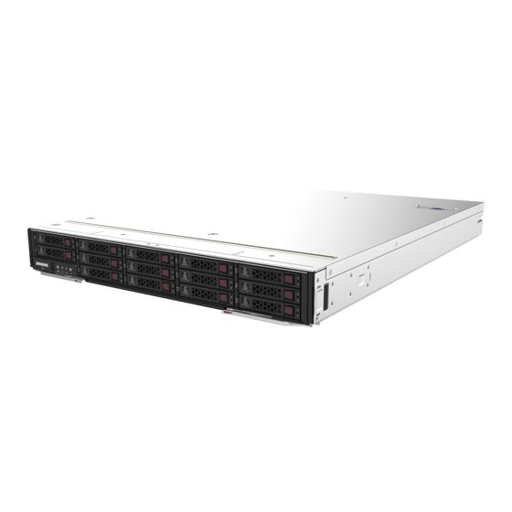
Server models and chassis view H3C UniServer B5800 G3 blade server is an H3C-proprietary blade server with a maximum of two Intel Purley or Jintide C series processors. The server provides strong storage performance and flexible expansion capability. It can be installed in an H3C UniServer B16000 blade server enclosure and managed through the OM management module in a centralized way. -
Page 56: Components
1 × serial port connector (expanded by using the SUV cable) Expansion Maximum 4 × PCIe 3.0 slots (one for a storage controller, three for mezzanine modules) slots Components Figure 2 H3C B5800 G3 server components Item Description (1) Chassis Centralizes blade server components. - Page 57 Item Description One of the most important parts of a server, on which multiple components are installed, such as a processor, memory, and PCIe (3) System board module. It is integrated with basic server components, including the BIOS chip, HDM chip, and PCIe connectors. Refers to PCIe modules connected by the mezzanine connectors.
-
Page 58: Front Panel
Front panel Front panel view of the server Figure 3 Front panel Table 1 Front panel description Item Description The slot is available for: • SAS/SATA HHDs/SSDs (numbered 0). • 2 × SATA M.2 SSD modules in an M.2 SSD adapter (numbered 0 and 1 for the left to the right). -
Page 59: Suv Cable
activated by using the following methods: Press the UID button LED. Activate the UID LED from HDM. • Flashing blue: 1 Hz—The firmware is being upgraded or the system is being managed from HDM. Do not power off the server. 4 Hz—HDM is restarting. -
Page 60: Serial Label Pull Tab
Table 3 SUV cable connectors Item Description Application Serial port Diagnoses faults and debugs devices. VGA connector Connects terminal displays such as monitors or KVM devices. The extended USB 2.0 connectors and USB 3.0 connector that comes with the default configuration are all available for the following USB devices: 2 ×... -
Page 61: System Board Components
System board components System board layout Figure 6 System board layout Table 4 System board components Item Description Drive backplane connector 1... -
Page 62: Dimm Slots
Item Description Storage controller connector Drive backplane connector 2 SATA M.2 SSD module connector 2 SATA M.2 SSD module connector 1 Drive backplane connector 3 System battery Drive backplane connector 4 TPM/TCM connector NVMe VROC module connector USB 3.0 connector Mezzanine module connector 3 (for processor 1, ICM 3/6) Mezzanine module supporting bracket 2 Micro SD card connector 2... -
Page 63: System Maintenance Switch
Figure 7 System board DIMM slot layout System maintenance switch Table 5 describes how to use the maintenance switch. For more information about the position of the maintenance switch, see "System board components". Table 5 System maintenance switch description Item Description Remarks •... -
Page 64: Pcie Connectors
PCIe connectors Table 6 PCIe devices and slave processors PCIe PCIe PCIe connector connector PCIe device PCIe device Processor standard physical form factor bandwidth bandwidth NVMe drive 6 Processor 1 PCIe 3.0 2.5 inches NVMe drives 7 to 14 Processor 2 PCIe 3.0 2.5 inches Non-standard... -
Page 65: Storage Requirements
Figure 8 Internal networking of a blade server LOM P1 LOM P2 Embedded Mezz1 Mid-plane Mezz2 Mezz3 Blade Storage requirements Follow these guidelines to store storage media: • As a best practice, do not store an HDD for 6 months or more without powering on and using it. •... -
Page 66: Appendix B Component Specifications
Appendix B Component specifications For components compatible with the server and detailed component information, contact Technical Support. HDDs and SSDs Drive numbering The blade server provides drive number (drive slot number) marks on the front panel to help identify drives, as shown in Figure Figure 9 Drive numbering at the front Drive LEDs... -
Page 67: Sata M.2 Ssd Module Leds
Fault/UID LED status Present/Active LED status Description The drive is performing a RAID migration or Flashing green (4.0 Hz) rebuilding, or the system is reading or writing data to the drive. The drive is present but no data is being Steady green read or written to the drive. -
Page 68: Dimms
Steady/Flashing green An M.2 SSD module is faulty. Replace the drive Steady amber (4 Hz) immediately. Steady/Flashing green An M.2 SSD module is operating correctly and is selected Steady blue (4 Hz) by the RAID controller. An M.2 SSD module is performing a RAID migration or Flashing green (4 Hz) rebuilding, or the system is reading or writing data to the drive. - Page 69 Callout Description Remarks Options include: • 1R— One rank (Single-Rank). • 2R—Two ranks (Dual-Rank). A 2R DIMM is equivalent to two 1R DIMMs. Number of ranks • 4R—Four ranks (Quad-Rank). A 4R DIMM is equivalent to two 2R DIMMs • 8R—Eight ranks (8-Rank).
-
Page 70: Appendix C Managed Hot Removal Of Nvme Drives
BIOS user guide for the server. To perform a managed hot removal of the NVMe drive when VMD is disabled, contact H3C Support. When VMD is configured as Auto or Enabled, NVMe drive hot removal is not supported in SLES operating systems. -
Page 71: Performing A Managed Hot Removal In Linux
Figure 13 Removing the NVMe drive Observe the LEDs on the NVMe drive. Make sure the Fault/UID LED is steady blue. ® Make sure the NVMe drive is removed from the Devices list of Intel Rapid Storage Technology enterprise. Remove the NVMe drive. For more information about the removal procedure, see "Removing an NVMe drive."... - Page 72 Remove the NVMe drive. For more information about the removal procedure, see "Removing an NVMe drive."...
-
Page 73: Appendix D Environment Requirements
Appendix D Environment requirements About environment requirements The operating temperature requirements for the server vary depending on the server model and hardware configuration. When the general and component-based requirements conflict, use the component-based requirement. Be aware that the actual maximum operating temperature of the server might be lower than what is stated because of poor site cooling performance. - Page 74 Maximum server operating Hardware options temperature • Processors with a TDP not more than 150 W are supported excluding processor 6240, 6252, 6148, 6136, 6128, 6144, 5222, 5122, 5220R, 6126T, 6208U, 6226R, and 8160T. 45°C (113°F) • SATA M.2 SSDs are not supported. •...
-
Page 75: Appendix E Product Recycling
Appendix E Product recycling New H3C Technologies Co., Ltd. provides product recycling services for its customers to ensure that hardware at the end of its life is recycled. Vendors with product recycling qualification are contracted to New H3C to process the recycled hardware in an environmentally responsible way. -
Page 76: Appendix F Glossary
Appendix F Glossary Item Description Asynchronous DRAM Refresh is a platform process which flushes the data in ADR protected write buffers to DCPMM when the system power unit detects power loss from the AC power supply. Basic input/output system is non-volatile firmware pre-installed in a ROM chip on a server's management module. -
Page 77: Appendix G Acronyms
Appendix G Acronyms Acronym Full name Asynchronous DRAM Refresh BIOS Basic Input/Output System Central Processing Unit DCPMM Data Center Persistent Memory Module Double Data Rate DIMM Dual Inline Memory Module DRAM Dynamic Random Access Memory Graphics Processing Unit Host Bus Adapter Hard Disk Drive Hardware Device Management Interconnect Module... - Page 78 Acronym Full name Secure Digital Small Form Factor Solid State Drive Trusted Cryptography Module Thermal Design Power Trusted Platform Module Unit Identification Ultra Path Interconnect Universal Serial Bus VROC Virtual RAID on CPU Volume Management Device...
Need help?
Do you have a question about the UniServer B5800 G3 and is the answer not in the manual?
Questions and answers