
Related Manuals for H3C UniServer B5700 G5


Summary of Contents for H3C UniServer B5700 G5
- Page 1 H3C UniServer B5700 G5 Blade Server User Guide New H3C Technologies Co., Ltd. http://www.h3c.com Document version: 6W100-20230218...
- Page 2 The information in this document is subject to change without notice. All contents in this document, including statements, information, and recommendations, are believed to be accurate, but they are presented without warranty of any kind, express or implied. H3C shall not be liable for technical or editorial errors or omissions contained herein.
- Page 3 Preface This preface includes the following topics about the documentation: • Audience. • Conventions. • Documentation feedback. Audience This documentation is intended for: • Network planners. • Field technical support and servicing engineers. • Server administrators working with the Server. Conventions The following information describes the conventions used in the documentation.
- Page 4 Symbols Convention Description An alert that calls attention to important information that if not understood or followed WARNING! can result in personal injury. An alert that calls attention to important information that if not understood or followed CAUTION: can result in data loss, data corruption, or damage to hardware or software. An alert that calls attention to essential information.
- Page 5 Documentation feedback You can e-mail your comments about product documentation to info@h3c.com. We appreciate your comments.
-
Page 6: Table Of Contents
Contents Safety information ·························································································· 1 General operating safety ···································································································································· 1 Electrical safety ·················································································································································· 1 Battery safety ····················································································································································· 1 ESD prevention ·················································································································································· 2 About the Blade Server ·················································································· 2 Product Overview ··············································································································································· 3 Technical parameters········································································································································· 3 Product specifications ································································································································ 3 Technical parameters ································································································································· 4 Components ·······················································································································································... - Page 7 Configuring the blade server ········································································ 34 Configuration flowchart ···································································································································· 35 Default login parameters ·································································································································· 35 Connecting the blade server to a network········································································································ 36 Connecting through the management module ························································································· 36 Connecting through ICMs ························································································································ 37 Verifying the blade server status ······················································································································ 37 Modifying default parameters ···························································································································...
- Page 8 Installing a mezzanine network adapter ··································································································· 52 Replacing a SATA M.2 SSD ···························································································································· 52 Operation scenario ··································································································································· 53 Prerequisites ············································································································································ 53 Removing a SATA M.2 SSD module ······································································································· 53 Installing a SATA M.2 SSD module ········································································································· 53 Replacing a SATA M.2 SSD adapter ··············································································································· 54 Operation scenario ···································································································································...
- Page 9 Maintenance operation····································································································································· 73 Task list ···················································································································································· 73 Observing LED status ······························································································································ 74 Monitoring the temperature and humidity in the equipment room ···························································· 74 Viewing server status ······························································································································· 74 Collecting server logs ······························································································································· 74 Updating firmware for the server ·············································································································· 74...
-
Page 10: Safety Information
In practice, the safety information includes but is not limited to what are mentioned in this document. General operating safety • Only H3C-authorized personnel or professional engineers can run the device. • Place the device on a clean, stable workbench or floor for servicing. •... -
Page 11: Esd Prevention
• Do not disassemble, crush, puncture, short external contacts, or dispose of the battery in fire or water. • Dispose of the battery at a designated facility. Do not throw the battery away together with other wastes ESD prevention Electrostatic charges that build up on people and tools might damage or shorten the lifespan of the system board and electrostatic-sensitive components. -
Page 12: Product Overview
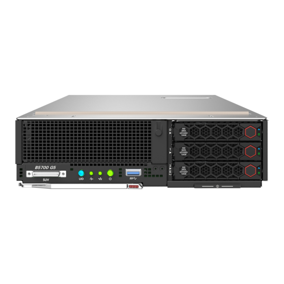
Product Overview H3C UniServer B5700 G5 server (hereinafter referred to as the blade server) is an H3C-proprietary blade server with a maximum of two Intel Whitley Ice Lake series processors or Montage Jintide C3 series processors. The server provides strong computing performance and flexible expansion capability. -
Page 13: Technical Parameters
Feature Description The graphics card chip (model: AST2500) is integrated into the BMC chip. With 64 MB video memory, it supports maximum resolution of 1920 x 1080@60 Hz (32 bpp). Resolution description: Integrated • 1920 x 1080: Indicates that there are 1920 pixel columns horizontally and 1080 pixel graphics columns vertically. -
Page 14: Components
Components This sections describes components of the blade server. Figure 2 Components of the blade server Table 3 Description of blade server components Name Description Chassis cover One of the most important parts of a blade server, on which multiple components are installed, such as a CPU, memory, and PCIe module. -
Page 15: Front Panel
Name Description Ensures adequate cooling of the blade server. Install a filler panel Drive filler panel when no drive is installed on the blade server. Drive backplane Powers the drive and provides a data transfer channel. Blade server chassis Centralizes blade server parts and components. Provides data storage media for blade servers, and supports hot Drive swapping. -
Page 16: Leds And Buttons
Table 4 Description of front panel components Item Description • Optional riser card (for processor 2) Optional SAS/SATA drive or NVMe drive Optional SAS/SATA drive or SATA M.2 SSD module (via the adapter module) Pull-out asset label USB 3.0 port Buttons for releasing the locking levers Locking levers SUV connector... -
Page 17: Suv Cable
Description Status • Flashing red (1 Hz)—A critical alarm is present. • Steady green—A link is present on the port. Embedded GE • Flashing green—The port is receiving or sending data. network adapter LED • Off—No link is present on the port. •... -
Page 18: Serial Asset Label Pull Tab
Item Description Application • USB optical drives for installing operating systems. Serial asset label pull tab The serial label pull tab is on the front panel, as shown in "Front panel components." It provides the following information about the blade server: •... -
Page 19: Dimm Slots
Item Description Mezzanine module connector 2 (for processor 2, ICM 2/5) Mezzanine module connector 3 (slave processor 1, ICM 2/6) Mezzanine module supporting bracket Mezzanine module connector 1 (for processor 1, ICM 1/4) Backplane connector System battery Drive backplane connector TPM/TCM connector Storage controller connector System maintenance switch... - Page 20 Figure 8 System maintenance switch The following problems can be solved with the system maintenance switch. Table 8 describes meanings of the system maintenance switch and "System board layout" shows the layout. • Users forget the HDM login user name or password and cannot log in to HDM. •...
-
Page 21: Pcie Connector
PCIe connector NOTE: If a CPU is absent, the corresponding PCIe devices are not available. Table 9 CPUs to which the PCIe devices correspond PCIe PCIe PCIe PCIe connector connector PCIe device form factor device standard physical bandwidth bandwidth • •... -
Page 22: Drive Leds
Figure 9 Drive numbering Drive LEDs The blade server supports SAS, SATA, and NVMe drives, of which SAS and SATA drives support hot swapping. You can use the LEDs on a drive to identify its status. Figure 10 shows the location of the LEDs on a drive. -
Page 23: Sata M.2 Ssd Module
Table 11 NVMe drive LED description Drive Drive fault/UID present/active Description LED status LED status Flashing amber (0.5 The managed hot removal is complete, and you are allowed to remove the drive. Flashing amber (4 The drive is in hot insertion. Steady/Flashing Steady amber The drive is faulty. -
Page 24: Drive Backplane
Fault/UID LED Present/Active LED Description status status selected by the RAID controller. An M.2 SSD module is performing a RAID migration Flashing (4.0 Hz) or rebuilding, or the system is reading or writing data to the drive. An M.2 SSD module drive is present but no data is Steady on being read or written to the drive. -
Page 25: Internal Networking
Figure 12 3SFF drive backplane Table 13 3SFF drive backplane component Description Silkscreen Data, AUX and power 3-in-1 connector Internal networking The blade server access the network through an interconnection module. The interconnection module provides the internal interconnection with blade servers through the infix backplane, and provides uplink interconnection interfaces for blade servers through the panel interfaces. -
Page 26: B/D/F Information About The Server
Figure 13 Internal wiring method of the blade server chassis LOM P1 LOM P2 Embedded Mezz1 Mid-plane Mezz2 Mezz3 Blade B/D/F information about the server The B/D/F information of the server may change with the PCIe card configuration. Users can obtain the B/D/F information of the server through the following ways: •... -
Page 27: Component Installation Guidelines
Component installation guidelines SAS/SATA drive • The drives are hot swappable. • As a best practice, install drives that do not contain RAID information. • If you are using the drives to create a RAID, follow these restrictions and guidelines: To avoid degraded RAID performance or RAID creation failures, make sure all drives in the RAID are the same type (HDDs or SSDs) and have the same connector type (SAS or SATA). -
Page 28: Riser Card And Pcie Card
Table 14 NVMe VROC module specifications Model Description Supported RAID level NVMe VROC module Intel edition, NVMe-VROC-Key-i RAID 0/1/5/10 supports Intel NVMe drives only. NVMe VROC module advanced NVMe-VROC-Key-P edition, supports any brand of RAID 0/1/5/10 NVMe drives. NVMe VROC module standard NVMe-VROC-Key-S edition, supports any brand of RAID 0/1/10... -
Page 29: Storage Controller And Its Power Fail Safeguard Module
Installation guidelines When a storage controller is installed onto the storage controller connector on the system board, no riser card and PCIe card can be installed on the blade server. For the specific location of the storage controller connector, see "System board layout."... - Page 30 For a PMC storage controller, the status of the flash card becomes Abnormal_status code. You can check the status code to identify the exception. For more information, see H3C Servers HDM Online Help. For an LSI supercapacitor, the status of the flash card displayed by HDM becomes ...
-
Page 31: Gpu
HDM will generate SDS log records. For details on how to query the SDS log, see H3C Servers HDM Online Help. • When the supercapacitor expires, it needs to be replaced in time. Otherwise, the power fail data safeguard function of the storage controller will fail. -
Page 32: Sata M.2 Ssd Adapter Module
• For efficient use of storage, use SATA M.2 SSD modules that have the same capacity to build a RAID. If the SATA M.2 SSD modules have different capacities, the lowest capacity is used across all SATA M.2 SSD modules in the RAID. SATA M.2 SSD adapter module The SATA M.2 SSD adapter module supports hot swapping. - Page 33 DIMM specifications can be identified by the label on it. Figure 14 DIMM identification Table 19 Description of DIMM identification Description Definition • 8 GB • 16 GB Capacity • 32 GB • 1R = The number of ranks is 1. •...
- Page 34 Standard ECC can correct 1-bit memory errors and detects multi-bit memory errors. When standard ECC detects multi-bit errors, it informs the server and stops the server. Independent mode can prevent multi-bit errors from occurring on the server, and correct 1-bit or 4-bit memory errors (when the errors are located on the same DDR4 on the DIMM).
- Page 35 NOTE: You can query the DIMM frequency and the maximum DIMM frequency supported by the CPU with server-compatible part query tool. In the query tool, query the DIMM frequency by the part name of "memory module". Query the maximum DIMM frequency supported by the CPU by the part name of "processor".
- Page 36 Figure 15 1-CPU DIMM configuration guidelines DIMM population schemes CPU 1 Number of DIMMs ● 1 DIMM ● ● 2 DIMMs 4 DIMMs ● ● ● ● ● ● ● ● ● ● 6 DIMMs ● ● ● ● ● ●...
- Page 37 PMem 200 DIMMs installed on the server must be the same. For details on the product code, see the server-compatible part query tool. The frequency of the DIMM installed for each CPU must not exceed the maximum DIMM frequency supported by the CPU. For the frequency of the DIMM and the maximum DIMM frequency supported by the CPU, see the server-compatible part query tool.
-
Page 38: Cpu
Guidelines You can install one or two processors. • To avoid damage to a processor or the system board, only H3C authorized or professional server engineers can install, replace, or remove a processor. • Make sure the processors on the server are the same model. -
Page 39: Installing Or Removing The Blade Server
Meaning of CPU product model suffix If the CPU model is UN-CPU-INTEL-8360Y-S, then it is suffixed with "Y" (abbreviated as CPU model suffix). You can query the CPU model supported by the server with the server-compatible part query tool. Table 22 describes meaning of the Intel Ice Lake CPU model suffix. -
Page 40: Installing The Blade Server
• Wear an ESD wrist strap and make sure it makes good skin contact and is reliably grounded. • Do not wear any conductive objects, such as jewelry or watches. • Before removing the blade server, make sure you back up the data, stop all services, and power off the server. -
Page 41: Prerequisites
Table 23 Blade server power-on methods Power-on method Application scenario • The blade server is installed and the chassis is not powered Powering on the blade server together with the enclosure Powering on the blade server by pressing the power on/standby button The chassis is powered on, the blade server is installed but is in a... -
Page 42: Powering Off The Blade Server
Method 5: Power on the blade server through the blade server HDM Web UI. The blade server can be powered on through the power management function of the blade server HDM Web UI. For the specific operations, see the H3C Servers HDM Online Help. Powering off the blade server This section describes how to power off the blade server. -
Page 43: Guidelines
The blade server can be powered off through the power management function of the blade server HDM Web UI. For the specific operations, see the H3C Servers HDM Online Help. Powering off the server forcedly by pressing the power on/standby button... -
Page 44: Configuration Flowchart
Configuration flowchart Figure 21 Configuration flowchart Start Connect the blade server to a network Power on the blade server Verify the blade server status Modify OM default login parameters Modify HDM default login parameters Log in to the blade server Configure the BIOS Configure RAID Install operating system and... -
Page 45: Connecting The Blade Server To A Network
Table 25 Default OM parameters Item Default value Username Admin Password Password@_ IP address of the 192.168.100.100/24 management port The default IP address, default username and password for the blade server HDM management port are shown in Table Table 26 Default HDM parameters Item Default value Username... -
Page 46: Connecting Through Icms
Connecting through ICMs The mezzanine network adapter on each blade server has a corresponding ICM. To connect a blade server to the network through an ICM, make sure the corresponding ICM are present. For more information about mezzanine network adapter and ICM mapping relations, see "Internal networking."... -
Page 47: Modifying The Default Ip Address Of Hdm
Log in to HDM. For more information, see "Accessing the blade server HDM." Modify the HDM default IP address. For more information, see H3C Servers HDM Online Help Logging into the blade server operating system For more information, see "Logging in to the blade server operating system."... -
Page 48: Configuring Raid
For the difference between the administrator and user privileges and guidelines for setting the BIOS passwords, see the BIOS user guide for the server. Configuring RAID Configure physical and logical drives (RAID arrays) for the server. The supported RAID levels and RAID configuration methods vary by storage controller model. For more information, see the storage controller user guide for the server. -
Page 49: Replaceable Parts And Their Videos
Replaceable parts and their videos Set out below are the specific method of replacing each part and the replaceable parts of the server: • SAS/SATA drive (Replacing a SAS/SATA drive) • NVMe drive (Replacing an NVMe drive) • Riser card and PCIe card (Replacing the riser card and PCIe card) •... -
Page 50: Prerequisites
Prerequisites Take the following ESD prevention measures: • Wear antistatic clothing. • Wear an ESD wrist strap and make sure it makes good skin contact and is reliably grounded. • Do not wear any conductive objects, such as jewelry or watches. •... -
Page 51: Verifying The Replacement
Log in to OM. For more information, see the OM online help. Log in to HDM. For more information, see H3C Servers HDM online help. Access the BIOS. For more information, see the storage controller user guide for the server. -
Page 52: Removing An Nvme Drive
• Do not wear any conductive objects, such as jewelry or watches. • Identify the position of the drive to be replaced. • To replace a drive that is installed with an operating system and is not configured with a RAID or is in a non-redundancy array, back up data, stop all services, and power off the blade server. -
Page 53: Verifying The Replacement
• Verify the drive properties (including capacity) by using one of the following methods: Log in to HDM. For more information, see H3C Servers HDM Online Help. Log in to OM. For more information, see the OM online help. -
Page 54: Removing The Riser Card And Pcie Card
• Replace the blade server. • When you replace a component, examine the slot and connector for damages. Make sure the pins are not damaged (bent for example) and do not contain any foreign objects. • You might also remove other components. For the removed components to be reinstalled correctly, record their positions and connections before removal, for example, taking pictures of cable connection and drive installation positions, or labeling cables. -
Page 55: Replacing The Storage Controller And Its Power Fail Safeguard Module
Replacing the storage controller and its power fail safeguard module This section describes the detailed operating steps for replacing the storage controller and its power fail safeguard module. Operation scenario • The storage controller fails. • Replace the storage controller with another model. •... -
Page 56: Removing The Storage Controller And Its Power Fail Safeguard Module
• Remove the blade server. • When you replace a component, examine the slot and connector for damages. Make sure the pins are not damaged (bent for example) and do not contain any foreign objects. • You might also remove other components. For the removed components to be reinstalled correctly, record their positions and connections before removal, for example, taking pictures of cable connection and drive installation positions, or labeling cables. -
Page 57: Replacing The Straight-Through Card
b. Use the 0404A0X1 extension cable to connect the supercapacitor to the storage controller. Install the chassis cover. Place the chassis cover horizontally downward as aligning the mushroom-shaped head on the chassis cover with the groove on the chassis, and slide the chassis cover toward the front of the server until it is locked. -
Page 58: Installing The Straight-Through Card
Remove the straight-through card. Remove two screws, hold the middle of the straight-through card, lift the straight-through card horizontally, and then put the straight-through card into an ESD bag Installing the straight-through card Install the straight-through card. Remove the straight-through card to be installed from the ESD bag, and insert it downward by aligning it with the connector on the main board. -
Page 59: Removing The Gpu Card
• Remove the blade server. • When you replace a component, examine the slot and connector for damages. Make sure the pins are not damaged (bent for example) and do not contain any foreign objects. • You might also remove other components. For the removed components to be reinstalled correctly, record their positions and connections before removal, for example, taking pictures of cable connection and drive installation positions, or labeling cables. -
Page 60: Prerequisites
• Expand the standard PCIe NIC or mezzanine NIC. • Replace the standard PCIe NIC with another model. • The standard PCIe NIC or mezzanine NIC hinders the maintenance of other parts. Prerequisites Take the following ESD prevention measures: • Wear antistatic clothing. -
Page 61: Removing A Mezzanine Network Adapter
b. (Optional) Remove the PCIe card filler panel. Lift the filler panel up and remove it from the riser card. c. InstallIng PCIe card to riser card connector Insert the PCIe NIC along the PCIe connector on the riser card, and then close the PCIe card fixing buckle. Install the riser card with the PCIe NIC in the blade server. -
Page 62: Operation Scenario
Operation scenario • Expand the SATA M.2 SSD module. • The SATA M.2 SSD module fails. • The SATA M.2 SSD module hinders maintenance of other parts • Replace the SATA M.2 SSD module with full space. • Replace the SATA M.2 SSD module with another model. Prerequisites Take the following ESD prevention measures: •... -
Page 63: Replacing A Sata M.2 Ssd Adapter
Configure RAID for the SATA M.2 SSD module. For the specific methods, see the storage controller user guide of the product. Replacing a SATA M.2 SSD adapter This section describes the detailed steps for replacing the SATA M.2 SSD adapter module. Operation scenario •... -
Page 64: Installing A Sata M.2 Ssd Adapter
Installing a SATA M.2 SSD adapter To learn the specific installation guidelines of the SATA M.2 SSD adapter module, see "SATA M.2 SSD adapter module." Take the SATA M.2 SSD adapter out of the antistatic bag, and insert the SATA M.2 SSDs into the adapter. -
Page 65: Removing The Nvme Vroc Module
• You might also remove other components. For the removed components to be reinstalled correctly, record their positions and connections before removal, for example, taking pictures of cable connection and drive installation positions, or labeling cables. Removing the NVMe VROC module Remove the access panel. -
Page 66: Prerequisites
Prerequisites Take the following ESD prevention measures: • Wear antistatic clothing. • Wear an ESD wrist strap and make sure it makes good skin contact and is reliably grounded. • Do not wear any conductive objects, such as jewelry or watches. •... -
Page 67: Verifying The Replacement
Log in to OM and verify the memory capacity of the DIMM. For more information, see the OM online help. • Using HDM: Log in to HDM and verify the memory capacity of the DIMM. For more information, see H3C Servers HDM Online Help. • Using BIOS: Access the BIOS, select Socket Configuration >... -
Page 68: Prerequisites
Prerequisites Take the following ESD prevention measures: • Wear antistatic clothing. • Wear an ESD wrist strap and make sure it makes good skin contact and is reliably grounded. • Do not wear any conductive objects, such as jewelry or watches. •... -
Page 69: Installing A Processor
CAUTION: Be sure to paste the barcode label delivered with the processor on the side of the radiator to cover the original barcode label on the radiator; otherwise H3C will be unable to provide subsequent warranty service for the processor. -
Page 70: Verifying The Replacement
• Log in to OM. For more information, see the OM online help. • Log in to HDM. For more information, see H3C Servers HDM Online Help. Expanding the processor For details, see the quick installation guide of processor. Installing and setting up a TCM or TPM This section introduces the detailed installation steps of the TPM/TCM module and how to enable the TPM/TCM module functions. -
Page 71: Installing And Setting Up A Tpm Or Tcm
• Before installing, make sure that you back up the data, stop all services, and power off the server. For more information, see "Powering off the blade server." • Remove the blade server. • When you replace a component, examine the slot and connector for damages. Make sure the pins are not damaged (bent for example) and do not contain any foreign objects. -
Page 72: Installing A Tcm Or Tpm
Installing a TCM or TPM Remove the access panel. Press the unlock button on the access panel, slide the panel to the server rear, and lift the access panel. (Optional) Remove the riser card and PCIe card that prevent you from accessing the TPM/TCM connector. -
Page 73: Configuring Encryption In The Operating System
• H3C is not liable for blocked data access caused by improper use of the TCM or TPM. For more information, see the encryption technology feature documentation provided by the operating system. -
Page 74: Replacing The System Battery
Replacing the system battery This section describes the detailed steps for replacing the system battery. Operation scenario The server comes with a system battery (Panasonic BR2032) installed on the system board, which supplies power to the real-time clock and has a lifespan of 3 to 5 years. •... -
Page 75: Installing The System Battery
For environment protection purposes, dispose of the used-up system battery at a designated site. Installing the system battery Install the system battery. a. Insert the system battery with the plus sign "+" facing up into the system battery holder. b. Press down the battery to secure it into place. (Optional) If the the mezzanine NIC has been removed, install it. -
Page 76: Removing The System Board
• You might also remove other components. For the removed components to be reinstalled correctly, record their positions and connections before removal, for example, taking pictures of cable connection and drive installation positions, or labeling cables. Removing the system board CAUTION: •... -
Page 77: Operation Scenario
Operation scenario • The drive backplane fails. • The drive backplane hinders maintenance of other parts. Prerequisites Take the following ESD prevention measures: • Wear antistatic clothing. • Wear an ESD wrist strap and make sure it makes good skin contact and is reliably grounded. •... -
Page 78: Common Operations
Install the removed drives. Install the blade server. Power on the blade server. For more information, see "Powering on the blade server." Common operations NOTE: The software interfaces are subject to change without notice. Figures in this section are for illustration only. - Page 79 Figure 24 Connecting the VGA connector Plug the other end of the video cable into the VGA connector of the display terminal and fix it using the screws on both sides of the plug. As shown in Figure 25, plug one end of the USB connector of the USB-PS2 cable into the USB connector extended from the server SUV cable, and connect the PS2 connectors at the other end to the mouse and keyboard respectively.
-
Page 80: Remote Login
Remote login Log in to OM. Enter https://OM_IP_address in the browser and press Enter. On the page that opens, enter the OM username and password, and then click Login. Figure 26 Logging in to OM Log in to the blade server. As shown in Figure 27, click Compute Node Management >... -
Page 81: Maintenance
Figure 28 Logging in to OM Log in to the HDM web UI. As shown in Figure 29, click Compute Node Management > Corresponding Blade Server > Remote Console > Authentication-free on the OM management page. Figure 29 Logging in to HDM Maintenance The following information describes the guidelines and tasks for daily server maintenance. -
Page 82: Maintenance Tools
• Regularly check the server from HDM or OM for operating health issues. • Keep the operating system and software up to date as required. • Make a reliable backup plan: Back up data regularly. If data operations on the server are frequent, back up data as needed in shorter intervals ... - Page 83 • To view basic information and status of the subsystems of the server, see "View device information" in H3C Servers HDM Online Help. Collecting server logs For the procedure for collecting server logs, see collecting logs in the OM online help.
- Page 84 Contents Appendix A Part specifications ····································································· 1 Appendix B Technical support ······································································ 2 Collecting server information······························································································································ 2 Preparing debugging tools ································································································································· 2 Appendix C Product recycling ······································································· 3 Appendix D Glossary ···················································································· 4 Appendix E Acronyms ·················································································· 5...
-
Page 85: Appendix A Part Specifications
Appendix A Part specifications Query all the parts supported by the server and their details through the official website Server-compatible Part Query Tool. Operating ambient temperature specification Table 1 Operating ambient temperature specification Maximum temperature Temperature CPU mode 35°C 40°C 45°C The CPU with 165 The CPU models 6314U,... -
Page 86: Appendix B Technical Support
Appendix B Technical support If you encounter any complicated problems during daily maintenance or troubleshooting, contact H3C Support. Collecting server information Before contacting H3C Support, collect the following server information to facilitate troubleshooting: • Log and sensor information. • Product serial number. -
Page 87: Appendix C Product Recycling
Appendix C Product recycling New H3C Technologies Co., Ltd. provides product recycling services for its customers to ensure that hardware at the end of its life is recycled. Vendors with product recycling qualification are contracted to New H3C to process the recycled hardware in an environmentally responsible way. -
Page 88: Appendix D Glossary
Appendix D Glossary Table 2 Glossary Item Description Basic input/output system is non-volatile firmware pre-installed in a ROM chip on a server's management module. The BIOS stores basic input/output, power-on BIOS self-test, and auto startup programs to provide the most basic hardware initialization, setup and control functionality. -
Page 89: Appendix E Acronyms
Appendix E Acronyms Table 3 Acronyms Acronym Full name BIOS Basic Input Output System Central Processing Unit Double Data Rate DIMM Dual Inline Memory Module DRAM Dynamic Random Access Memory Graphics Processing Unit Host Bus Adapter Hard Disk Drive Hardware Device Management Interconnect Module Large Form Factor LRDIMM... - Page 90 Acronym Full name Solid State Drive Speed Select Technology Trusted Cryptography Module Thermal Design Power Trusted Platform Module Unit Identification Ultra Path Interconnect Universal Serial Bus VROC Virtual RAID on CPU Volume Management Device...
Need help?
Do you have a question about the UniServer B5700 G5 and is the answer not in the manual?
Questions and answers