
Related Manuals for H3C UniServer BT716F


Summary of Contents for H3C UniServer BT716F
- Page 1 H3C UniServer BT716F Straight-Through Module User Guide New H3C Technologies Co., Ltd. http://www.h3c.com Document version: 6W100-20230224...
- Page 2 The information in this document is subject to change without notice. All contents in this document, including statements, information, and recommendations, are believed to be accurate, but they are presented without warranty of any kind, express or implied. H3C shall not be liable for technical or editorial errors or omissions contained herein.
- Page 3 Preface This preface includes the following topics about the documentation: • Audience. • Conventions. • Documentation feedback. Audience This documentation is intended for: • Network planners. • Field technical support and servicing engineers. • Network administrators working with the server. Conventions The following information describes the conventions used in the documentation.
- Page 4 Symbols Convention Description An alert that calls attention to important information that if not understood or followed WARNING! can result in personal injury. An alert that calls attention to important information that if not understood or followed CAUTION: can result in data loss, data corruption, or damage to hardware or software. An alert that calls attention to essential information.
- Page 5 Documentation feedback You can e-mail your comments about product documentation to info@h3c.com. We appreciate your comments.
-
Page 6: Table Of Contents
Contents 1 Safety ··················································································································································· 1-1 1.1 Safety Information ····························································································································· 1-1 1.1.1 General Operating Safety ······································································································· 1-1 1.1.2 Electrical Safety ······················································································································ 1-1 1.2 Safety Precautions ···························································································································· 1-1 1.3 ESD Prevention ································································································································· 1-1 1.3.1 Preventing Electrostatic Discharge ························································································ 1-1 1.3.2 Grounding Methods to Prevent Electrostatic Discharge ························································ 1-2 2 About the BT716F Straight-Through Module ·······················································································... - Page 7 4.2 Powering Off the Straight-Through Module ······················································································ 4-1 5 Checking the Straight-Through Module ······························································································· 5-1 5.1 Checking Port Status of Straight-Through Module Through OM Modules ······································· 5-1 5.1.2 Viewing through the OM CLI ·································································································· 5-2 6 Configuring the Straight-Through Module ···························································································· 6-1 6.1 Changing the Port Rate ····················································································································...
-
Page 8: Safety
1.1.1 General Operating Safety • Only H3C authorized or professional engineers are allowed to operate the device. • Keep the device clean and dust-free. Do not place it in a humid place or allow liquids to enter •... -
Page 9: Grounding Methods To Prevent Electrostatic Discharge
• Transport or store the device in an ESD bag. • Place the device on a grounded table before taking it out of the ESD bag. • Avoid touching pins or circuitry of the device without taking any ESD prevention measures. 1.3.2 Grounding Methods to Prevent Electrostatic Discharge When removing or installing the device, you can use one or multiple of the following grounding methods to prevent electrostatic discharge:... -
Page 10: About The Bt716F Straight-Through Module
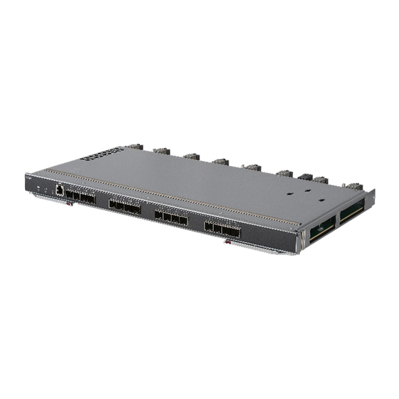
2.1 Product Overview H3C UniServer BT716F is a 16G/32G FC straight-through module for the H3C UniServer B16000 blade enclosure. It provides an external data interface, which enables direct connection of parallel cables to the FC Mezz NIC port of the blade server at the front of the chassis. -
Page 11: Interface
Category Item Description Maximum 3.35 kg weight Maximum Power power 25 W consumption consumption • Operating temperature: 5°C to 45°C Temperature • Storage temperature: -40°C to 70°C • Operating humidity: 8% to 90% (non-condensing) Humidity Environment • Storage humidity: 5% to 95% (non-condensing) specifications •... -
Page 12: Description Of Interfaces
Figure 2-2 Interfaces 2.3.2 Description of Interfaces Figure 2-3 shows the external interfaces on the panel of a straight-through module. Table 2-2 lists details about the interfaces. - Page 13 Figure 2-3 External interfaces Table 2-2 Description of interfaces Interface Quan Type Interfaces Description Name tity This serial port is used to access the AMC CLI. It is only used by RJ-45 technical support engineers to display the status of the 32G FC AMC serial port optical port or for maintenance.
-
Page 14: Indicators
• 1 to 16 Each port supports three rate modes (auto/16G/32G). auto (default mode) indicates that the port is adaptive to the rate of the optical module. The port rate can be changed with the OM module. For details, see 6.1 Changing the Port Rate. - Page 15 Figure 2-4 Indicators of the straight-through module Indicators for different interfaces of the straight-through module are consistent-looking. Here we use one indicator of interface as an example. Table 2-3 Description of indicators Name Color Status • Steady on blue: The UID indicator is activated (through the OM module).
-
Page 16: Internal Connection
Maximum Number of Connections Between Straight-Through Model of Blade Server Supported Mezz NICs Modules and Mezz NICs H3C UniServer B5700 G5 2.5.1 1. Mode 1 H3C UniServer B5700 G3 2.5.1 1. Mode 1. H3C UniServer B7800 G3 2.5.1 1. Mode 1. - Page 17 • Mezz NIC 2 is connected to straight-through modules in slot 2 and slot 5. • Mezz NIC 3 is connected to straight-through modules in slot 3 and slot 6. Figure 2-5 Connections between straight-through modules and blade server Mezz NICs (1) LOM P1 LOM P2 Embedded...
-
Page 18: Internal Connections Between Straight-Through Modules And Blade Server Mezz Nics
Figure 2-6 Connections between straight-through modules and blade server Mezz NICs (2) LOM P1 LOM P2 Embedded Mezz1 Mid-plane Mezz2 Mezz3 Mezz4 Mezz5 Mezz6 Blade 2.5.2 Internal Connections Between Straight-Through Modules and Blade Server Mezz NICs When configuring the Mezz NIC of the blade server, you need to specify the connection between the Mezz NIC port and the straight-through module. - Page 19 Table 2-5 Correspondence between external interfaces of the straight-through module and the blade servers Correspondence between external Maximum Number of Model of Blade Server interfaces of the straight-through module and Supported Mezz NICs the blade servers 2.5.3 1. Correspondence between Half-width single-height blade external interfaces of the straight-through server...
- Page 20 As shown in Figure 2-8, when the half-width single-height blade server is installed in the front slots of the chassis, the external interfaces of the straight-through module have one-to-one correspondence with the 16 blade servers. That is, port 1 is connected to blade server 1, and users can access blade server 1 through port 1;...
- Page 21 Figure 2-9 Numbering of slots for the full-width single-height blade server As shown in Figure 2-10, if the front of the chassis is configured with full-width single-height blade servers supporting up to six Mezz NICs, every two external interfaces of the straight-through module correspond to a full-width single-height blade server.
- Page 22 Figure 2-10 Internal connections between external interfaces of straight-through module and full-width single-height blade server (supports up to 6 Mezz NICs) Port 16 Blade15 Port 15 Port 14 Blade13 Port 13 Front Port 4 Blade3 Port 3 Port 2 Blade1 Port 1 Mid-plane 3.
- Page 23 Figure 2-11 Internal connection between straight-through module external interfaces in slots 1, 3, 4, and 6 and the full-width single-height blade server (up to 3 Mezz NICs) Port 16 Blade15 Port 15 Port 14 Front Blade13 Port 13 ICM 1/3/4/6 Port 4 Blade3 Port 3...
-
Page 24: Logical Structure
Figure 2-12 Internal connections between external interfaces of straight-through module (slots 2 and 5) and full-width single-height blade server (supports up to 3 Mezz NICs) Blade15 Port 16 Port 15 Blade13 Port 14 Front Port 13 ICM 2/5 Blade3 Port 4 Port 3 Blade1 Port 2... -
Page 25: Installation Guidelines
Figure 2-13 Logical structure Mid-plane 16*16G 2*GE MDIO 2*PHY 16*16G FC RJ45 2.7 Installation Guidelines • As shown in Figure 2-14, up to 6 straight-through modules can be installed in the chassis, and the installation slots are ICM 1 to ICM 6 at the rear of the chassis. •... - Page 26 Figure 2-14 Straight-through module installation guidelines (1): ICM1 slot (2): ICM2 slot (3): ICM3 slot (4): ICM4 slot (5): ICM5 slot (6): ICM6 slot 2-17...
-
Page 27: Hardware Compatibility
2.8 Hardware Compatibility This section describes the compatibility between straight-through modules and Mezz NICs and the compatibility between straight-through modules and optical modules. 2.8.1 Compatibility Between Straight-Through Modules and Mezz NICs Table 2-6 describes the compatibility between the BT616E straight-through module and the Mezz NIC. -
Page 28: External Networking Connection
• H3C SFP/SFP+ modules are recommended as straight-through modules. • The types of H3C SFP/SFP+ modules may change over time. If you need accurate information about module types, consult H3C marketing or technical support personnel. • For specific specifications of each optical module, see H3C Transceiver Modules User Guide. -
Page 29: Replacing The Icm
Replacing the ICM 3.1 Scenario • The straight-through module is faulty. • The straight-through module needs to be replaced by a switching module or straight-through module in another model. 3.2 Installation Tools The following tools or devices may be required when you install, use, and maintain the equipment. Table 3-1 Required tools Table 3-2 Tool requirements Image... -
Page 30: Preparations
(for example, check whether pins are deformed or whether foreign objects are on the connectors). • Understand the guidelines for installing the ICM, as described in 2.7 Installation Guidelines. 3.4 Replacement Procedure Note For specific procedures, see http://www.h3c.com/cn/home/qr/default.htm?id=354. - Page 31 Remove the ICM. Press the unlock button on the ICM to fully open the ejector, and slowly pull the ICM out of the chassis horizontally. Put the ICM into the ESD bag. Install the ICM. Take out the ICM to be installed from the ESD bag. Press the unlock button to automatically open the ejector.
-
Page 32: Powering On And Powering Off
Powering On and Powering Off This section describes how to power on/off the straight-through module. 4.1 Powering On the Straight-Through Module The straight-through module is automatically powered on when the chassis is powered on. Upon successful power-on, the Health indicator is steady green. For specific location of the indicator, see Indicators. -
Page 33: Checking The Straight-Through Module
Checking the Straight-Through Module Note For ease of understanding, the data in this section is only for reference. During operation, the actual data should prevail. 5.1 Checking Port Status of Straight-Through Module Through OM Modules With OM, you can view the port connection status of the BT716F straight-through module. Table Shows the query modes. -
Page 34: Viewing Through The Om Cli
5.1.2 Viewing through the OM CLI 1. Prerequisites To view the port connection status of straight-through module through the OM CLI, you need to make the following preparations: • Power on the straight-through module: See 4.1 Powering On the Straight-Through Module. -
Page 35: Configuring The Straight-Through Module
Configuring the Straight-Through Module 6.1 Changing the Port Rate You can log in to the OM web UI and switch the port rate of straight-through module. 1. Prerequisites To change the port rate of straight-through module through the OM Web UI, you need to make the following preparations: •... - Page 36 2. Procedures As shown in Figure 6-1, connect the Ethernet interface of the PC to the MGMT interfaces of the active or standby OM module through the LAN. Ensure that the IP addresses of the PC and OM module are accessible on L3. Figure 6-1 Setting up the hardware environment Enclosure ①...
-
Page 37: Logging In To The Cli Of Om Module
Figure 6-2 Logging in to the web UI of the OM module 6.2.2 Logging In to the CLI of OM Module 1. Prerequisites • Power on the chassis. Obtain the login data of the OM module. The default data for logging in to the OM module CLI is shown in Table 6-2. - Page 38 After login, the OM CLI displays the login page, as shown below. ****************************************************************************** * Copyright (c) 2004-2019 New H3C Technologies Co., Ltd. All rights reserved.* * Without the owner's prior written consent, * no decompiling or reverse-engineering shall be allowed.
-
Page 39: Firmware Upgrade
Firmware Upgrade For specific procedures, see H3C UniServer B16000 Upgrade Guide. - Page 40 Contents Appendix A Technical support ······································································ 1 Collecting fault information ································································································································· 1 Preparing the maintenance tools ······················································································································· 1 Appendix B Product recycling ······································································· 2 Appendix C Glossary ···················································································· 3 Appendix D Acronyms ·················································································· 4...
-
Page 41: Appendix A Technical Support
Appendix A Technical support If you encounter any complicated problems during daily maintenance or troubleshooting, contact Technical Support. Collecting fault information Before contacting Technical Support, collect the following server information to facilitate troubleshooting: • Log and sensor information about the straight-through module. •... -
Page 42: Appendix B Product Recycling
Appendix B Product recycling New H3C Technologies Co., Ltd. provides product recycling services for its customers to ensure that hardware at the end of its life is recycled. Vendors with product recycling qualification are contracted to New H3C to process the recycled hardware in an environmentally responsible way. -
Page 43: Appendix C Glossary
Appendix C Glossary Item Description A module that supports hot swapping (a hot-swappable module) can be installed or Hot swapping removed while the server is running without affecting the system operation. A mechanism that ensures high availability and business continuity by providing backup Redundancy modules. -
Page 44: Appendix D Acronyms
Appendix D Acronyms Acronym Full name App Engine Auxiliary Management Controller Command-Line Interface Fiber Channel FCoE Fibre Channel over Ethernet FCoE Forwarder Interconnect module Intelligent Resilient Framework Mezz Mezzanine N_Port Virtualization Onboard Manager Serial Over LAN Secure Shell Unit identification...
Need help?
Do you have a question about the UniServer BT716F and is the answer not in the manual?
Questions and answers