Table of Contents
Advertisement
Quick Links
Advertisement
Table of Contents
Troubleshooting

Related Manuals for Omron SYSMAC C200H-FZ001


Summary of Contents for Omron SYSMAC C200H-FZ001
- Page 1 Cat. No. W208-E1-2 SYSMAC C200H-FZ001 Fuzzy Logic Unit...
- Page 2 C200H-FZ001 Fuzzy Logic Unit Operation Manual Revised September 1999...
- Page 3 OMRON. No patent liability is assumed with respect to the use of the information contained herein. Moreover, because OMRON is constantly striving to improve its high-quality products, the information contained in this manual is subject to change without notice.
- Page 4 About this Manual: This manual describes the operation of the C200H-FZ001 Fuzzy Logic Unit and includes the sections described below. The C200H-FZ001 is used in conjunction with Fuzzy Support Software. Refer to the Fuzzy Support Software Operation Manual for details on the use of the Fuzzy Support Software. Please read this manual completely and be sure you understand the information provide before attempt- ing to operate the C200H-FZ001.
-
Page 5: Table Of Contents
TABLE OF CONTENTS PRECAUTIONS ..........Intended Audience . - Page 6 Table of contents SECTION 6 – Maintenance and Troubleshooting ....Maintenance ........... . . Troubleshooting .
-
Page 7: Precautions
PRECAUTIONS This section provides general precautions for using the C200H-FZ001 Fuzzy Logic Unit and related devices. The information contained in this section is important for the safe and reliable application of the C200H-FZ001 Fuzzy Logic Unit. You must read this section and understand the information contained before attempting to set up or oper- ate the C200H-FZ001 Fuzzy Logic Unit. -
Page 8: Intended Audience
It is extremely important that a PC and all PC Units be used for the specified purpose and under the specified conditions, especially in applications that can directly or indirectly affect human life. You must consult with your OMRON representative before applying a PC system to the above-mentioned applications. -
Page 9: Operating Environment Precautions
Application Precautions The PC outputs may remain ON or OFF due to deposition or burning of the output relays or destruction of the output transistors. As a countermeasure for such problems, external safety measures must be provided to ensure safety in the system. - Page 10 Application Precautions Caution Failure to abide by the following precautions could lead to faulty operation of the PC or the system, or could damage the PC or PC Units. Always heed these pre- cautions. Fail-safe measures must be taken by the customer to ensure safety in the event of incorrect, missing, or abnormal signals caused by broken signal lines, momentary power interruptions, or other causes.
- Page 11 Application Precautions Before touching a Unit, be sure to first touch a grounded metallic object in order to discharge any static build-up. Not doing so may result in malfunction or dam- age.
-
Page 12: Section 1 - Introduction
SECTION 1 Introduction This section introduces the features of the Fuzzy Logic Unit and explains the fuzzy logic processing that takes place during operation. Features ............Configuration . -
Page 13: Features
Section 1-2 Configuration Features The C200H-FZ001 Fuzzy Logic Controller brings advanced, high-speed fuzzy logic technology to the C200H PC. Control of some complicated systems that previously had to be supervised by a specialist can now be handled by the C200H. Large I/O Capacity The C200H-FZ001 provides 8 inputs and 4 outputs, and each rule can have up to 8 condition and 2 conclusion parts, allowing it to be used in a wide range of... -
Page 14: Fuzzy Logic Theory
Section 1-3 Fuzzy Logic Theory Fuzzy Logic Theory 1-3-1 Introduction to Fuzzy Logic Before fuzzy logic theory, modern control methods required a precise expres- sion (either theoretical or numerical) of the relationship between inputs and out- puts in a system. Instead of a precise mathematical formula, fuzzy logic expres- ses the relationship between inputs and outputs in a group of if/then statements based on human know-how and experience. - Page 15 Section 1-3 Fuzzy Logic Theory If the water is hot, turn the faucet a little to the left. If the water is warm, don’t turn the faucet. If the water is cool, turn the faucet a little to the right. If the water is cold, turn the faucet far to the right.
- Page 16 Section 1-3 Fuzzy Logic Theory bership functions are called labels. The following diagram shows a standard ar- rangement of Λ-type membership functions. Labels: NL: Negative Large NM: Negative Medium NS: Negative Small ZR: Zero Range PS: Positive Small PM: Positive Medium PL: Positive Large (-) Min.
-
Page 17: Fuzzy Logic In The C200H-Fz001
Section 1-3 Fuzzy Logic Theory After all of the rule grades are calculated, the grade for each label is calculated. The grade for a label is called its fuzzy output. The fuzzy output is the maximum rule grade for that label. The maximum value is taken because the rules are linked by logical ORs. - Page 18 Section 1-3 Fuzzy Logic Theory Membership functions are made up of connecting line segments and are de- fined by the end points of the line segments. Up to four end points (defining three line segments) can be entered. The grade at the end points must be between 0 and 1 (between 000 and FFF) and an end point must have a grade of 0 or 1 (000 or FFF) at the edges of the input range.
- Page 19 Section 1-3 Fuzzy Logic Theory When the operation shown in the previous diagram is performed for all of the labels, each label will have a fuzzy output. Label Label Label Label Label Label Label Output data Defuzzification Defuzzification calculates the final result of the fuzzy logic processing from the fuzzy outputs.
-
Page 20: Developing The Knowledge Base
Section 1-3 Fuzzy Logic Theory In the following diagram, F , and F are equal and the final result (R) would be equal to S if the leftmost label location were specified, or S if the rightmost label location were specified. Label Label Label... - Page 21 Section 1-3 Fuzzy Logic Theory 1, 2, 3... 1. The following diagrams show two versions of conventional-fuzzy hybrid control systems. The first uses fuzzy logic in parallel with the existing control system and the second uses fuzzy logic to refine the output of the existing control system.
- Page 22 Section 1-3 Fuzzy Logic Theory There must be at least one output from a rule at all times. An error will occur if there isn’t an output, so be sure not to allow gaps in input coverage such as the one shown below.
-
Page 23: Downloading The Knowledge Base
Section 1-3 Fuzzy Logic Theory er range for greater sensitivity. In the diagram on the right, the central section of each membership function has no sensitivity to changes in the input value. Greater sensitivity in this region. No influence from neighboring membership functions and no sensitivity to changes in input value in these regions. -
Page 24: Section 2 - Components And Switch Settings
SECTION 2 Components and Switch Settings This section describes the components of the C200H-FZ001 and their functions. Components ............Indicators . -
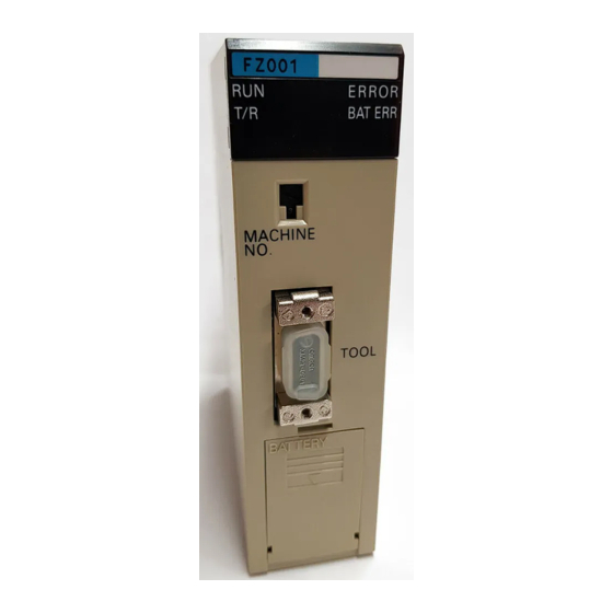
Page 25: Components
Section 2-3 Switch Settings Components Front: Back: LED indicators Indicate operational status. DIP switch 1 DIP switch 2 Unit number switch Used to set the unit number. RS-232C port Connects to the computer. Indicators The LED indicators on the front of the Fuzzy Logic Unit provide visual informa- tion on the general operation of the Unit. - Page 26 Section 2-3 Switch Settings DIP Switch 1 Pins 5 to 8 of DIP switch 1 are used to set the data format for RS-232C port com- munications, as shown in the following table. Pins 1 to 4 are not used. Leave these pins in their factory settings.
-
Page 27: Rs-232C Interface
Request to send Clear to send Not used Not used Enable receive Signal ground Connector: XM3B-0922 (OMRON) or equivalent (set includes connector cover and plug) Recommended cable: AWG28x5P IFVV-SB (Fujikura Densen) Cable length: 15 m max. C200H-FZ001/Computer Connect the cable to the Unit only after turning off the computer. -
Page 28: Dimensions
Section 2-4 RS-232C Interface Dimensions Dimensions for the C200H-FZ001 are shown below. All dimensions are in milli- meters. 10.7 100.5 34.5 200* Backplane *Allow a total of approximately 200 mm for cable clearance. -
Page 29: Section 3 - Memory Allocation
SECTION 3 Memory Allocation This section explains how words in the C200H are allocated to the Fuzzy Logic Unit, and the function of those words as flags, control bits, and I/O words. Memory Allocation in the C200H ........IR Area Words . -
Page 30: Memory Allocation In The C200H
Section 3-2 IR Area Words Memory Allocation in the C200H As a Special I/O Unit, the Fuzzy Logic Unit will be allocated 10 words in the IR Area of the C200H according to the unit number set on the front of the Unit, as shown below. - Page 31 Section 3-2 IR Area Words First Input Word IR 1n1 specifies the address of the word that contains the data for the first input. The leftmost digit specifies the data area and the rightmost 3 digits specify the word in that area. The rightmost 3 digits must be BCD, but the leftmost digit can take any of the values shown in the table below.
-
Page 32: I/O Data Format
Section 3-3 I/O Data Format 2. Bits not used in IR 1n4 cannot be used as work words in the program. I/O Data Format The Fuzzy Logic Unit receives input data from the C200H CPU, calculates the results for up to four outputs, and outputs those results to the C200H CPU. This section describes the structure of that input and output data. - Page 33 Section 3-3 I/O Data Format The Error Flag (ER) will be turned ON when any of bits 0 to 4 for that output are turned ON. The following table shows the function of the error code bits. Flag name Function Input Range Exceeded Flag Turned ON to indicate that the input range has been exceeded.
-
Page 34: Section 4 - Program And Knowledge Base
SECTION 4 Program and Knowledge Base This section explains how to prepare the two basic software requirements for Fuzzy Logic Unit operation: the sub-program used in the C200H and the knowledge base used in the Fuzzy Logic Unit itself. C200H Sub-program . -
Page 35: C200H Sub-Program
Section 4-1 C200H Sub-program C200H Sub-program A sub-program must be prepared within the C200H program to control the trans- fer of data between the C200H and the Unit. This program can be written with standard instructions such as MOV(21). The four basic steps in this sub-pro- gram are listed below. - Page 36 Section 4-1 C200H Sub-program The ladder diagram and mnemonics for inputting these settings are shown be- low. 00000 MOV(21) #0008 MOV(21) #0100 MOV(21) #0003 MOV(21) #0110 Address Instruction Operands Address Instruction Operands 00000 00000 00003 MOV(21) 00001 MOV(21) 0003 0008 00004 MOV(21) 00002...
- Page 37 Section 4-1 C200H Sub-program Input Data Transfer and Fuzzy Processing Initialization The unit number of the Analog Input Units (Special I/O Units) are set to 0 and 1, so the digital input data will be stored automatically in IR 100 to IR 104 and IR 110 to IR 114.
-
Page 38: Making And Downloading The Knowledge Base
Section 4-2 Making and Downloading the Knowledge Base Output Data Transfer The results of the fuzzy logic processing and error codes are output automatical- ly to the words beginning at the First Output Address, so it isn’t always necessary to transfer the output data, but in this case the data must be transferred to the words allocated to the Analog Output Units. - Page 39 Section 4-2 Making and Downloading the Knowledge Base The operations that can be performed with the FSS are described briefly in a table below. Refer to the Fuzzy Support Software Operation Manual for details on these FSS operations. Operation Function File management Making a new Clears the knowledge base file being...
-
Page 40: Section 5 - Example Application
SECTION 5 Example Application This section describes the development of an actual control system that uses a C200H-FZ001 Fuzzy Logic Unit. Conveyor Belt Control System Summary ....... Making the Knowledge Base . -
Page 41: Conveyor Belt Control System Summary
Section 5-1 Conveyor Belt Control System Summary Conveyor Belt Control System Summary In this example application, a Fuzzy Logic Unit is used to control two conveyor belts for product packaging. The products are carried on conveyor A at random intervals, but at a fixed speed. The boxes are carried at regular intervals on con- veyor B, which runs parallel to conveyor A at a speed controlled by the Fuzzy Logic Unit. - Page 42 Section 5-1 Conveyor Belt Control System Summary System Configuration Motor A Encoder A Servodriver A Manual adjustment Encoder A Motor B Encoder B Servodriver B Encoder B Connecting conveyor PH 1 to 4 (photoelectric sensors) C200H Analog Analog Fuzzy C200H- Input Unit Output Unit Counter A...
-
Page 43: Making The Knowledge Base
Section 5-2 Making the Knowledge Base Fuzzy logic processing using these rules and rules based on the rate of change of the product/box offset allow very smooth adjustment of conveyor B’s speed. Note We assume that only one product or box travels between the photoelectric sen- sors at a time. - Page 44 Section 5-2 Making the Knowledge Base Offset Rate of Change Conveyor B Speed Adjustment...
-
Page 45: Creating Rules
Section 5-2 Making the Knowledge Base 5-2-3 Creating Rules Expressing the Rules Start creating the rules by organizing your “know-how” or “past experience” of the system in everyday expressions. A good way to organize these expressions is a table like the one below. About even Product is ahead Box is ahead... -
Page 46: I/O Allocation And Ladder Program
Section 5-3 I/O Allocation and Ladder Program IF E=PS AND DE=PS THEN VB=PS IF E=PS AND DE=ZR THEN VB=PS IF E=PS AND DE=NS THEN VB=PM IF E=PS AND DE=NL THEN VB=PM IF E=PL AND DE=PL THEN VB=PM IF E=PL AND DE=PS THEN VB=PM IF E=PL AND DE=ZR THEN VB=PM IF E=PL AND DE=NS THEN VB=PL IF E=PL AND DE=NL THEN VB=PL... - Page 47 Section 5-3 I/O Allocation and Ladder Program High-speed Counter Units (Units Number 0 and 1) Word Content Function DM 1000 0400 Specifies Gate mode for Unit A (unit number 0). DM 1001 0001 Specifies internal inputs for Unit A. DM 1100 0400 Specifies Gate mode for Unit B (unit number 1).
-
Page 48: Ladder Program
Section 5-3 I/O Allocation and Ladder Program 5-3-3 Ladder Program The ladder diagram sub-program that controls the conveyor belt system is shown below. Refer to 5-3-4 Adjusting I/O Data for a description of special as- pects of the following program. 25313 TIM 010 Servodriver preparation... - Page 49 Section 5-3 I/O Allocation and Ladder Program 25315 MOV(21) #0000 DM0180 03000 CLC(41) SUB(31) Calculates the present pro- DM0110 duct/box offset. DM0120 DM0130 25504(CY) Turned ON if the box is 03110 ahead of the product. CLC(41) SUB(31) DM0180 DM0130 DM0130 03000 CLC(41) SUB(31)
- Page 50 Section 5-3 I/O Allocation and Ladder Program 03000 03110 ADD(30) Adjusts the product/box offset #2048 data to be centered about 2048. DM0140 DM0145 03110 SUB(31) #2048 DM0140 DM0145 25504(CY) MOV(21) #0000 DM0145 CLC(41) 03000 03111 ADD(30) Adjusts the rate of change of the offset #2048 data to be centered about 2048.
- Page 51 Section 5-3 I/O Allocation and Ladder Program 25315 MOV(21) Sets the Scaling ON Flags #000C for Inputs 1 and 2 of the Analog Input Unit. MOV(21) Specifies the Number of Inputs. #0002 MOV(21) Specifies the First Input #0170 Address (DM 0170). MOV(21) Specifies the Number of Outputs.
- Page 52 Section 5-3 I/O Allocation and Ladder Program 03000 CMP(20) DM0106 DM0108 25507(<) ADD(30) DM0106 DM0162 DM0162 CMP(20) DM0162 DM0108 25505(>) MOV(21) DM0108 DM0162 25507(<) MOV(21) DM0108 DM0162 03000 12508 MOV(21) Moves Servodriver A data (converted by the Analog Input Unit) to DM 0210. DM0210 03201 MOV(21)
-
Page 53: Adjusting I/O Data
Section 5-3 I/O Allocation and Ladder Program 03000 MUL(32) Adjusts the Fuzzy Logic DM0162 Unit final result by factor DM0104 set above. DM0165 MOV(21) DM0210 DM0185 SRD(75) DM0185 DM0185 03112 ADD(30) Calculates the output to con- DM0210 veyor B by adding the Fuzzy Logic Unit final result to the DM0165 conveyor A value. - Page 54 Section 5-3 I/O Allocation and Ladder Program In such a case, the output can be subdivided before being sent to the servodriv- er. In the ladder program for the conveyor belt control system, the output was subdivided and then multiplied by a scaling factor. This process produces smooth operation when the output from the Fuzzy Logic Unit is large and good response when the output is small.
-
Page 55: Section 6 - Maintenance And Troubleshooting
SECTION 6 Maintenance and Troubleshooting This section provides guidelines for dealing with routine maintenance and errors that might occur while using the Fuzzy Logic Unit. Maintenance ............Troubleshooting . -
Page 56: Maintenance
Section 6-1 Maintenance Maintenance The items listed in the following table should be inspected regularly to ensure correct operation. Area Item Correct condition Ambient conditions Temperature 0 to 55 C Humidity 35% to 85% (no condensation) Dust or debris No dust or debris should be allowed to accumulate on the Unit. Installation Unit mountings Check that the Unit is mounted securely. -
Page 57: Troubleshooting
Section 6-2 Troubleshooting Troubleshooting LED Error Indications The table below lists error conditions, their probable cause, and possible reme- dies. Indicator(s) Probable cause Remedy No indicators lit. The PC power supply is OFF. Connect the PC power supply or check connectors. -
Page 58: Error Processing
Section 6-3 Error Processing Error Processing Error Messages The following table lists errors that can occur in the C200H CPU due to Special I/O Units such as the Fuzzy Logic Unit, as well as the probable causes of the errors, their affect on PC operation, and possible remedies. Error and message FAL no. -
Page 59: Appendix
Appendix A Standard Models Name Model number Notes Fuzzy Logic Unit C200H-FZ001 Battery C200H-BAT09 One Battery is included with the Fuzzy Logic Unit. Fuzzy Support Software (FSS) C500-SU981-E The FSS is available on either 3.5” or 5.25” floppy disks. -
Page 60: B - Specifications
Appendix B Specifications Item Specification Fuzzy logic processor I/O capacity 8 inputs and 4 outputs max. Rule format 8 condition and 2 conclusion parts max. Number of rules 128 rules max. Logic process Forward logic Logic rule MAX–MIN logical product Number of labels 7 max. -
Page 61: Glossary
Glossary condition part The “if” clauses of a rule. A single rule can have up to 8 condition parts in the form “IF X AND X ... AND X .” center of gravity method A method of defuzzification. The center of gravity of the fuzzy outputs (along the x-axis) is calculated as the final result of fuzzy logic processing. -
Page 62: Index
Index Fuzzy Error Flag, 21 Input Range Exceeded Flag, 23 Memory Error Flag, 21 applications, precautions, ix No Corresponding Output Flag, 23 Processing Enabled Flag, 21 Results Output Flag, 21 Setting Error Flag, 21 Special I/O Unit error, 50 battery Too Few Input Words Flag, 23 life expectancy, 48 Too Many Input Words Flag, 23... - Page 63 Index ladder diagram program, example, 26 Restart Bits, Special I/O Unit, 50 RS 232C port cable specifications, 16 maintenance, 48 connector pins, 16 maximum value method. See defuzzification setting baud rate, 15 membership function setting protocol, 15 conclusion, standard shape, 12 rule grade condition calculating, 6...
Need help?
Do you have a question about the SYSMAC C200H-FZ001 and is the answer not in the manual?
Questions and answers