Siemens SIMATIC ET 200SP Manual
Hide thumbs
Also See for SIMATIC ET 200SP:
- System manual (409 pages) ,
- Manual (270 pages) ,
- Equipment manual (166 pages)
Table of Contents
Advertisement
Quick Links
Advertisement
Table of Contents

Related Manuals for Siemens SIMATIC ET 200SP


Summary of Contents for Siemens SIMATIC ET 200SP
- Page 2 ___________________ IM 155-6 PN HF interface module Preface (6ES7155-6AU00-0CN0) ET 200SP Documentation ___________________ Guide ___________________ SIMATIC Product overview ___________________ Wiring ET 200SP IM 155-6 PN HF interface module ___________________ (6ES7155-6AU00-0CN0) Parameters/address space ___________ Interrupts, error messages, diagnostics and system Manual alarms ___________________ Compatibility...
-
Page 3: Legal Information
Note the following: WARNING Siemens products may only be used for the applications described in the catalog and in the relevant technical documentation. If products and components from other manufacturers are used, these must be recommended or approved by Siemens. Proper transport, storage, installation, assembly, commissioning, operation and maintenance are required to ensure that the products operate safely and without any problems. -
Page 4: Security Information
Siemens recommends strongly that you regularly check for product updates. For the secure operation of Siemens products and solutions, it is necessary to take suitable preventive action (e.g. cell protection concept) and integrate each component into a holistic, state-of-the-art industrial security concept. - Page 5 Table of contents Preface ..............................4 ET 200SP Documentation Guide ......................7 Product overview ............................ 9 Properties ..........................9 Functions ..........................13 2.2.1 PROFIenergy .......................... 23 2.2.2 Configuration control (option handling) ................... 24 2.2.3 Use of fail-safe modules ......................24 2.2.4 Multi Hot Swap ........................
- Page 6 Table of contents IM 155-6 PN HF interface module (6ES7155-6AU00-0CN0) Manual, 03/2015, A5E03915895-AF...
- Page 7 ET 200SP Documentation Guide The documentation for the SIMATIC ET 200SP distributed I/O system is arranged into three areas. This arrangement enables you to access the specific content you require. Basic information The system manual describes in detail the configuration, installation, wiring and commissioning of the SIMATIC ET 200SP.
- Page 8 ET 200SP Documentation Guide Manual Collection ET 200SP The Manual Collection contains the complete documentation on the SIMATIC ET 200SP distributed I/O system gathered together in one file. You can find the Manual Collection on the Internet (http://support.automation.siemens.com/WW/view/en/84133942). My Documentation Manager The My Documentation Manager is used to combine entire manuals or only parts of these to your own manual.
-
Page 9: Product Overview
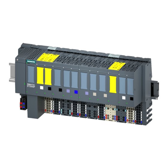
Product overview Properties Article number 6ES7155-6AU00-0CN0 View of the module Figure 2-1 View of the 155-6 PN HF interface module with accessories included in delivery IM 155-6 PN HF interface module (6ES7155-6AU00-0CN0) Manual, 03/2015, A5E03915895-AF... -
Page 10: Maximum Configuration
Product overview 2.1 Properties Properties The module has the following technical properties: ● Connects the ET 200SP distributed I/O system with PROFINET IO. ● Supply voltage 1L+ 24 V DC (SELV/PELV). The connection plug is included in the scope of delivery of the interface module. ●... - Page 11 ● BusAdapter BA SCRJ/RJ45 ● BusAdapter BA SCRJ/FC ● Labeling strips ● Reference identification label You can find more information on accessories in the ET 200SP distributed I/O system (http://support.automation.siemens.com/WW/view/en/58649293) system manual. IM 155-6 PN HF interface module (6ES7155-6AU00-0CN0) Manual, 03/2015, A5E03915895-AF...
-
Page 12: Server Module
Place the server module on the last slot of the configuration. If there are 64 I/O modules, the server module is plugged in slot 65. You can find more information in the Server module (http://support.automation.siemens.com/WW/view/en/63257531) manual. IM 155-6 PN HF interface module (6ES7155-6AU00-0CN0) Manual, 03/2015, A5E03915895-AF... - Page 13 Product overview 2.2 Functions Functions Introduction The interface module supports the following PROFINET IO functions: ● Integrated switch with 2 ports ● Supported Ethernet services: ping, arp, network diagnostics (SNMP)/MIB-2, LLDP-MIB and MRP-MIB ● Port diagnostics ● Deactivating of ports ●...
- Page 14 Product overview 2.2 Functions ● Station extension via ET-Connection ● The BusAdapter provides the connection system for PROFINET IO. The following versions are available for the IM 155-6 PN HF interface module: BusAdapter Up to firmware As of firmware 2.2 As of firmware For standard RJ45 connector: BA 2×RJ45...
- Page 15 GSD file V5.5 SP3 V5.5 SP3 with Portal) as of as of as of (http://support.auto with HSP 233 HSP 250/255 V12.0.1 with mation.siemens.co HSP 0058 m/WW/view/en/19 698639/130000)/s oftware from a third-party manu- facturer Real-time communication V2.0.0 Isochronous real-time V2.0.0...
-
Page 16: Real-Time Communication
You can find more information on this topic in the STEP 7 online help and ● As of STEP 7 V12, in the PROFINET with STEP 7 V13 (http://support.automation.siemens.com/WW/view/en/49948856) function manual. ● As of STEP 7 V5.5, in the system manual PROFINET System Description (http://support.automation.siemens.com/WW/view/en/19292127). - Page 17 You can find more information on the configuration of synchronized PROFINET devices in sync domains in the STEP 7 online help and ● As of STEP 7 V12, in the PROFINET with STEP 7 V13 (http://support.automation.siemens.com/WW/view/en/49948856) function manual. ● As of STEP 7 V5.5, in the system manual PROFINET System Description (http://support.automation.siemens.com/WW/view/en/19292127).
- Page 18 You can find more information on this topic in the STEP 7 online help and ● As of STEP 7 V12, in the PROFINET with STEP 7 V13 (http://support.automation.siemens.com/WW/view/en/49948856) function manual. ● As of STEP 7 V5.5, in the system manual PROFINET System Description (http://support.automation.siemens.com/WW/view/en/19292127).
- Page 19 You can find more information on this topic in the STEP 7 online help and ● As of STEP 7 V12, in the PROFINET with STEP 7 V13 (http://support.automation.siemens.com/WW/view/en/49948856) function manual. ● As of STEP 7 V5.5, in the system manual PROFINET System Description (http://support.automation.siemens.com/WW/view/en/19292127).
-
Page 20: Device Replacement
You can find more information on this topic in the STEP 7 online help and ● As of STEP 7 V12, in the PROFINET with STEP 7 V13 (http://support.automation.siemens.com/WW/view/en/49948856) function manual. ● As of STEP 7 V5.5, in the system manual PROFINET System Description (http://support.automation.siemens.com/WW/view/en/19292127). - Page 21 You can find more information on this topic in the STEP 7 online help and ● As of STEP 7 V12, in the PROFINET with STEP 7 V13 (http://support.automation.siemens.com/WW/view/en/49948856) function manual. ● As of STEP 7 V5.5, in the system manual PROFINET System Description (http://support.automation.siemens.com/WW/view/en/19292127).
-
Page 22: Shared Device
You can find more information on this topic in the STEP 7 online help and ● As of STEP 7 V5.5, in the system manual PROFINET System Description (http://support.automation.siemens.com/WW/view/en/19292127). Note In the case of a shared device application, make sure that all controllers work with the same send clock. - Page 23 PROFIenergy (for PROFINET) reduces the energy consumption by using PROFIenergy commands during production-free periods. Reference You can find more information on PROFIenergy in the ● I/O modules (http://support.automation.siemens.com/WW/view/en/55679691/133300) manual. ● Function manual PROFINET with STEP 7 V13 (http://support.automation.siemens.com/WW/view/en/49948856). ● PROFINET System Description (http://support.automation.siemens.com/WW/view/en/19292127) system manual.
-
Page 24: Configuration Control (Option Handling)
The IM 155-6 PN HF interface module as of firmware V2.1 supports the use of fail-safe modules. Reference You can find more information in the ET 200SP distributed I/O system (http://support.automation.siemens.com/WW/view/en/58649293) system manual. IM 155-6 PN HF interface module (6ES7155-6AU00-0CN0) Manual, 03/2015, A5E03915895-AF... - Page 25 BusAdapter during operation. Reference You can find more information on the removal/insertion of modules in the system manual ET 200SP distributed I/O system (http://support.automation.siemens.com/WW/view/en/58649293). IM 155-6 PN HF interface module (6ES7155-6AU00-0CN0) Manual, 03/2015, A5E03915895-AF...
-
Page 26: Pin Assignment
Wiring Pin assignment 24 V DC supply voltage The following table shows the signal names and the descriptions of the pin assignment for a 24 V DC supply voltage. Table 3- 1 Pin assignment 24 V DC supply voltage View Signal name Description Connector... - Page 27 Wiring 3.1 Pin assignment PROFINET IO with BusAdapter BA 2×RJ45 The following table shows the signal name and description of the pin assignment of the BusAdapter BA 2×RJ45. Table 3- 2 PROFINET IO pin assignment with BusAdapter BA 2×RJ45 View Signal name Description Transmit data +...
- Page 28 Wiring 3.1 Pin assignment PROFINET IO with BusAdapter BA 2×SCRJ The following table shows the signal name and description of the pin assignment of the BusAdapter BA 2×SCRJ. Table 3- 4 PROFINET IO pin assignment with BusAdapter BA 2×SCRJ View Signal Description name...
- Page 29 Receive data + RD_N Receive data - Reference You can find more information on accessories and how to connect the interface module in the system manual ET 200SP distributed I/O system (http://support.automation.siemens.com/WW/view/en/58649293). IM 155-6 PN HF interface module (6ES7155-6AU00-0CN0) Manual, 03/2015, A5E03915895-AF...
-
Page 30: Block Diagram
Wiring 3.2 Block diagram Block diagram Block diagram The following figure shows a block diagram of the interface module IM 155-6 PN HF. ① Switch 24 V DC supply voltage ② ET 200SP backplane bus interface and electronics M Ground ③... -
Page 31: Parameters/Address Space
I/O modules. Reference You can find more information on the control data record in the ET 200SP distributed I/O system (http://support.automation.siemens.com/WW/view/en/58649293) system manual and in the STEP 7 online help. IM 155-6 PN HF interface module (6ES7155-6AU00-0CN0) Manual, 03/2015, A5E03915895-AF... - Page 32 Parameters/address space 4.3 Substitute value behavior Substitute value behavior Substitute value behavior The respective output reacts according to its configured substitute value behavior: ● Current-free/voltage-free ● Output substitute value ● Keep last value The substitute value behavior is triggered in the following cases: ●...
- Page 33 IM 155-6 PN HF. You can find information on the status of the supply voltage L+ of the I/O modules in the Server module (http://support.automation.siemens.com/WW/view/en/63257531) manual. IM 155-6 PN HF interface module (6ES7155-6AU00-0CN0) Manual, 03/2015, A5E03915895-AF...
-
Page 34: Interrupts, Error Messages, Diagnostics And System Alarms
Interrupts, error messages, diagnostics and system alarms Status and error displays LED displays The following figure shows the LED displays on the interface module and BusAdapter. ① RN (green) ② ER (red) ③ MT (yellow) ④ PWR (green) ⑤ Available on BusAdapter BA 2xSCRJ only: MT2 (yellow) ⑥... - Page 35 Hardware or firmware defective (LEDs Run a firmware update. If the error persists, LK1 and LK2 of the PROFINET inter- contact Siemens Industry Online Support. face do not flash). Replace the interface module. * PWR LED on (on the interface module): Check the backplane bus for a short-circuit.
- Page 36 Interrupts, error messages, diagnostics and system alarms 5.1 Status and error displays PWR LED on the interface module Table 5- 2 Status display of the PWR LED PWR LED Meaning Remedy Supply voltage not present or too small. Check the supply voltage. Supply voltage present.
-
Page 37: Operating Principle
Interrupts, error messages, diagnostics and system alarms 5.1 Status and error displays LED display of configuration errors Configuration errors of the ET 200SP distributed I/O system are output on the interface module by the ERROR (red) and MAINT (yellow) LEDs. The following configuration errors are signaled by the LEDs: ●... -
Page 38: Error Display
Interrupts, error messages, diagnostics and system alarms 5.2 Interrupts Error display Table 5- 5 Error display Error type Error location Cause of error Solution (MAINT) (ERROR/ MAINT) Check the configuration No server module • of the ET 200SP. Interruptions on the backplane bus •... -
Page 39: Triggering A Hardware Interrupt
Interrupts, error messages, diagnostics and system alarms 5.2 Interrupts 5.2.1 Triggering of a diagnostics interrupt Triggering of a diagnostics interrupt For an incoming or outgoing event (e.g. wire break on a channel of an I/O module), the module triggers a diagnostic error interrupt if this is configured accordingly. The CPU interrupts processing of the user program and processes the diagnostic error interrupt OB (OB 82). -
Page 40: Diagnostics Alarms
Additional information on the data records for PROFINET IO The structure of the diagnostic data records and programming examples are available in the programming manual From PROFIBUS DP to PROFINET IO (http://support.automation.siemens.com/WW/view/en/19289930) and in Example application (http://support.automation.siemens.com/WW/view/en/24000238). IM 155-6 PN HF interface module (6ES7155-6AU00-0CN0) -
Page 41: Maintenance Events
5.3 Alarms Causes of error and troubleshooting The causes of error and remedies for the diagnostic alarms are described in the manuals for I/O modules (http://support.automation.siemens.com/WW/view/en/55679691/133300) in the section, "Interrupts, error messages, and system events". See also Channel diagnostics (Page 42) PROFINET with STEP 7 V11 (http://support.automation.siemens.com/WW/view/en/49948856) -
Page 42: Channel Diagnostics
Interrupts, error messages, diagnostics and system alarms 5.3 Alarms 5.3.3 Channel diagnostics Function Channel-related diagnostics provides information about channel faults in modules. Channel faults are mapped as channel diagnostics data in IO diagnostics data records. The data record is read using the instruction "RDREC". Structure of the diagnostics data records The data records supported by the ET 200SP distributed I/O system are based on the PROFINET IO standard - Application Layer Service Definition V2.2. - Page 43 Interrupts, error messages, diagnostics and system alarms 5.3 Alarms USI structure = W#16#0003 Table 5- 10 USI structure = W#16#0003 Data block name Content Comment Bytes W#16#0003 Manufacturer-specific diagnostics with failure of supply voltage L+ as of slot x of the ET 200SP module Followed by the slot as of which the supply voltage L+ has failed.
- Page 44 Interrupts, error messages, diagnostics and system alarms 5.3 Alarms USI structure = W#16#0006 Table 5- 12 USI structure = W#16#0006 Data block name Content Comment Bytes W#16#0006 Manufacturer-specific diagnostics if an ET 200SP I/O mod- ule is installed on an incorrect BaseUnit. Result: Station stop The I/O modules fail →...
- Page 45 Interrupts, error messages, diagnostics and system alarms 5.3 Alarms 5.3.4 Invalid configuration states of the ET 200SP on PROFINET IO Invalid configuration states The following invalid configuration states of the ET 200SP distributed I/O system lead to the failure of the IO device or prevent data exchange. ●...
-
Page 46: Stop Of The Io Controller And Recovery Of The Io Device
Interrupts, error messages, diagnostics and system alarms 5.3 Alarms 5.3.6 STOP of the IO controller and recovery of the IO device STOP of the SIMATIC IO controller Diagnostics received from the IO device while the IO controller is in STOP do not initiate a call of any corresponding OBs when the IO controller goes into RUN. - Page 47 Compatibility Compatibility of modules Compatibility with IM 155-6 PN HF interface module If you exchange or replace an interface module, the following table shows the compatibilities ● Between the interface modules IM 155-6 PN HF and IM 155-6 PN ST ●...
- Page 48 Compatibility 6.1 Compatibility of modules Status of the supply voltage Load voltage diagnostics are only valid if the station started up with a valid and complete configuration. ● For modules without parameter assignment in the following table, the status of the supply voltage (status byte of the server module) is always signaled as "1"...
- Page 49 Compatibility 6.1 Compatibility of modules AQ 4xU/I ST analog output module Note For operation of the AQ 4xU/I ST analog output module, firmware version V1.0 (6ES7135- 6HD00-0BA1) with the IM 155-6 PN HF interface module (6ES7155-6AU00-0CN0), you need to set the "Reaction to CPU STOP" parameter to "Turn off" with a PROFINET send clock <...
- Page 50 Compatibility 6.1 Compatibility of modules Operation with activated system redundancy S2 Note Restrictions in operation with activated system redundancy S2 You cannot use the following functions during operation of the IM155-6 PN HF, firmware version as of V3.0.0 with activated system redundancy S2: •...
-
Page 51: Technical Specifications
Technical specifications Technical specifications of the IM 155-6 PN HF Table 7- 1 Technical specifications of the IM 155-6 PN HF 6ES7155-6AU00-0CN0 Product type designation IM 155-6 PN HF with server module General information Firmware version V3.0 Product function I&M data Yes;... - Page 52 Technical specifications 6ES7155-6AU00-0CN0 Hardware configuration Rack Modules per rack, max. 64; + 16 ET 200AL modules Interfaces 1st interface Interface hardware Number of ports • Integrated switch • Yes; usable BusAdapters: BA 2xRJ45, BA 2xFC, BusAdapter (PROFINET) • BA 2xSCRJ (as of FS03), BA SCRJ/RJ45 (as of FS03), BA SCRJ/FC (as of FS03) Protocols PROFINET IO device...
- Page 53 Technical specifications 6ES7155-6AU00-0CN0 Open IE communication TCP/IP SNMP LLDP Isochronous mode Isochronous mode (application synchronized up to terminal) Constant bus cycle time Shortest clock pulse 250 µs Longest clock pulse 4 ms Bus cycle time (TDP), min. 250 µs Jitter, max. 1 µs Interrupts/diagnostics/status information Status display...
- Page 54 Technical specifications Technical specifications of the BusAdapter BA 2×RJ45 Table 7- 2 Technical specifications of the BusAdapter BA 2×RJ45 6ES7193-6AR00-0AA0 Interfaces PROFINET IO Number of PROFINET interfaces RJ45 Dimensions Width 20 mm Height 69.5 mm Depth 59 mm Weights Weight, approx. 46 g Technical specifications of the BusAdapter BA 2×FC Table 7- 3...
- Page 55 Technical specifications Technical specifications of the BusAdapter BA 2×SCRJ Table 7- 4 Technical specifications of the BusAdapter BA 2×SCRJ 6ES7193-6AP00-0AA0 Interfaces PROFINET IO Number of PROFINET interfaces 1; 2 ports (switch) SCRJ FO SCRJ Cable length 100 m • 50 m Plastic FOC (POF) •...
- Page 56 Technical specifications Technical specifications of the BusAdapter BA SCRJ/FC Table 7- 6 Technical specifications of the BusAdapter BA SCRJ/FC 6ES7193-6AP40-0AA0 Interfaces PROFINET IO Number of PROFINET interfaces 1; 2 ports (SCRJ + FC) FC (FastConnect) Yes; 1 x SCRJ Cable length 100 m •...
-
Page 57: Dimension Drawing
Dimension drawing This appendix contains a dimension drawing of the module mounted on a mounting rail. Always observe the specified dimensions for installation in cabinets, control rooms, etc. Figure A-1 Dimension drawing of the IM 155-6 PN HF interface module, front and side views IM 155-6 PN HF interface module (6ES7155-6AU00-0CN0) Manual, 03/2015, A5E03915895-AF...
Need help?
Do you have a question about the SIMATIC ET 200SP and is the answer not in the manual?
Questions and answers