Siemens SIMATIC ET 200SP Manual
Cpu 1512sp-1 pn 6es7512-1dk01-0ab0
Hide thumbs
Also See for SIMATIC ET 200SP:
- System manual (409 pages) ,
- Manual (270 pages) ,
- Equipment manual (166 pages)
Table of Contents
Advertisement
Advertisement
Table of Contents

Related Manuals for Siemens SIMATIC ET 200SP


Summary of Contents for Siemens SIMATIC ET 200SP
- Page 2 ___________________ CPU 1512SP-1 PN Preface (6ES7512-1DK01-0AB0) ___________________ Documentation guide ___________________ SIMATIC Product overview ___________________ Wiring ET 200SP CPU 1512SP-1 PN Interrupts, error messages, ___________ diagnostics and system (6ES7512-1DK01-0AB0) alarms ___________________ Manual Technical specifications ___________________ Dimension drawing 09/2016 A5E33591411-AC...
- Page 3 Note the following: WARNING Siemens products may only be used for the applications described in the catalog and in the relevant technical documentation. If products and components from other manufacturers are used, these must be recommended or approved by Siemens. Proper transport, storage, installation, assembly, commissioning, operation and maintenance are required to ensure that the products operate safely and without any problems.
-
Page 4: Preface
In order to protect plants, systems, machines and networks against cyber threats, it is necessary to implement – and continuously maintain – a holistic, state-of-the-art industrial security concept. Siemens’ products and solutions only form one element of such a concept. Customer is responsible to prevent unauthorized access to its plants, systems, machines and networks. - Page 5 This information is provided by the Siemens Industry Online Support in the Internet (http://www.siemens.com/automation/service&support). Industry Mall The Industry Mall is the catalog and order system of Siemens AG for automation and drive solutions on the basis of Totally Integrated Automation (TIA) and Totally Integrated Power (TIP).
-
Page 6: Table Of Contents
Table of contents Preface ..............................4 Documentation guide ..........................7 Product overview ..........................11 New functions in firmware version V2.0 ................. 11 Operating principle ......................... 14 Properties ..........................15 Operating and display elements .................... 20 2.4.1 Front view of the module with BusAdapter ................20 Mode switch ........................... -
Page 7: Documentation Guide
Documentation guide The documentation for the SIMATIC ET 200SP distributed I/O system is arranged into three areas. This arrangement enables you to access the specific content you require. Basic information The system manual describes in detail the configuration, installation, wiring and commissioning of the SIMATIC ET 200SP. - Page 8 You can download the product information free of charge from the Internet (https://support.industry.siemens.com/cs/us/en/view/73021864). Manual Collection ET 200SP The Manual Collection contains the complete documentation on the SIMATIC ET 200SP distributed I/O system gathered together in one file. You can find the Manual Collection on the Internet (http://support.automation.siemens.com/WW/view/en/84133942).
- Page 9 ● Manuals, characteristics, operating manuals, certificates ● Product master data You can find "mySupport" - CAx Data in the Internet (http://support.industry.siemens.com/my/ww/en/CAxOnline). Application examples The application examples support you with various tools and examples for solving your automation tasks. Solutions are shown in interplay with multiple components in the system - separated from the focus in individual products.
- Page 10 You can find the SIMATIC Automation Tool on the Internet (https://support.industry.siemens.com/cs/ww/en/view/98161300). PRONETA With SIEMENS PRONETA (PROFINET network analysis), you analyze the plant network during commissioning. PRONETA features two core functions: ● The topology overview independently scans PROFINET and all connected components.
-
Page 11: Product Overview
(ERP, asset thentication of the user. systems) OPC UA servers provide a large amount of data: To Siemens controllers with controllers • Values of PLC tags that clients can access • from other manufacturers Data types of these PLC tags •... - Page 12 Product overview 2.1 New functions in firmware version V2.0 New functions Applications Customer benefits Web server Backing up and re- You can, for example, backup and restore the You can make a backup copy of an operational storing via the Web configuration of the CPU to the PG/PC on project without STEP 7.
- Page 13 Product overview 2.1 New functions in firmware version V2.0 New functions Applications Customer benefits ET 200SP Support for ET 200AL You can set up a simple connection of IP You do not have to individually run sensors or in a central configura- 65/67 I/O to the CPU.
-
Page 14: Operating Principle
Product overview 2.2 Operating principle Operating principle The CPU contains the operating system and executes the user program. The user program is located on the SIMATIC memory card and is processed in the work memory of the CPU. The PROFINET interfaces on the CPU allow simultaneous communication with PROFINET devices, PROFINET controllers, HMI devices, programming devices, other controllers and other systems. -
Page 15: Properties
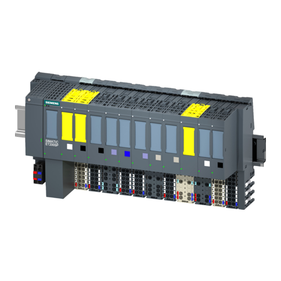
Product overview 2.3 Properties Properties Article number 6ES7512-1DK01-0AB0 View of the module The following figure shows the CPU 1512SP-1 PN. Figure 2-1 CPU 1512SP-1 PN CPU 1512SP-1 PN (6ES7512-1DK01-0AB0) Manual, 09/2016, A5E33591411-AC... - Page 16 The CM DP is optionally available with a PROFIBUS interface (X2). You can find additional information about this expansion module in the manual Communication module CM DP (http://support.automation.siemens.com/WW/view/en/90156526). You can find information about connecting the PROFINET IO BusAdapter to the CPU...
- Page 17 You can find a detailed description of the use of Motion Control and its configuration in the S7-1500 Motion Control (http://support.automation.siemens.com/WW/view/en/109739589) function manual. You can also use the TIA Selection Tool (http://w3.siemens.com/mcms/topics/en/simatic/tia-selection-tool) or the SIZER (http://w3.siemens.com/mcms/mc-solutions/en/engineering-software/drive-design-tool- sizer/Pages/drive-design-tool-sizer.aspx) to create or configure axes. – Integrated closed-loop control functionality...
- Page 18 Trace only supports saves measurements on a SIMATIC memory card. You will find additional information on "Trace" in the Using the trace and logic analyzer function (http://support.automation.siemens.com/WW/view/en/64897128) function manual. ● Integrated system diagnostics: –...
- Page 19 ● CPU 1512SP-1 PN supports the following additional functions: – PROFIenergy You can find information on the topic of "PROFIenergy" in the PROFINET function manual (https://support.industry.siemens.com/cs/ww/en/view/49948856) and in the PROFINET specification on the Internet (http://www.profibus.com). – Shared device You can find information on the topic of "Shared device" in the PROFINET function manual (https://support.industry.siemens.com/cs/ww/en/view/49948856).
-
Page 20: Operating And Display Elements
Product overview 2.4 Operating and display elements Operating and display elements 2.4.1 Front view of the module with BusAdapter The figure on the left shows the CPU 1512SP-1 PN including a plugged BA 2xRJ45 BusAdapter. The figure on the right shows a separate view of the BA 2xRJ45 BusAdapter. ①... -
Page 21: Mode Switch
Product overview 2.5 Mode switch Mode switch Use the mode switch to set the CPU operating mode. The following table shows the position of the switch and the corresponding meaning. Table 2- 2 Mode switch settings Position Meaning Explanation RUN mode The CPU is executing the user program. -
Page 22: Wiring
Wiring This section provides information on the pin assignment of the individual interfaces and the block diagram of the CPU 1512SP-1 PN. 24 V DC supply voltage (X80) The connector for the supply voltage is plugged in when the CPU ships from the factory. The figure below shows the pin assignment for 24 V DC supply voltage. - Page 23 Wiring PROFINET IO interface on the BusAdapter BA 2xRJ45 (X1 P1 R and X1 P2 R) The assignment at the BA 2xRJ45 BusAdapter corresponds to the Ethernet standard for an RJ45 connector. Table 3- 1 Pin assignment PROFINET IO interface on the BusAdapter BA 2xRJ45 View Designation When autonegotiation is deactivated, the RJ45 socket is...
- Page 24 Wiring PROFINET IO interface on the BusAdapter BA 2xFC (X1 P1 R and X1 P2 R) The following table shows the pin assignment for the PROFINET IO interface on the BusAdapter BA 2xFC. Table 3- 2 Pin assignment PROFINET IO interface on the BusAdapter BA 2xFC View Signal name Designation...
- Page 25 Wiring PROFINET IO interface with BusAdapter BA LC/RJ45 (X1 P1 R and X1 P2 R) (as of V2.0) The following table shows the signal names and description of the pin assignment for the BA LC/RJ45 BusAdapter. Table 3- 4 Pin assignment PROFINET IO with BusAdapter BA LC/RJ45 View Signal name Designation...
- Page 26 Wiring PROFINET IO interface with BusAdapter BA 2×SCRJ (X1 P1 R and X1 P2 R) The following table shows the signal names and description of the pin assignment for the BA 2×SCRJ BusAdapter. Table 3- 6 PROFINET IO pin assignment with BusAdapter BA 2×SCRJ View Signal Designation...
- Page 27 You can find additional information on the topics of "Connecting the CPU" and "Accessories/spare parts" in the system manual ET 200SP distributed I/O system (http://support.automation.siemens.com/WW/view/en/58649293). Assignment of the MAC addresses The MAC address is a globally unique device identifier that is assigned to each PROFINET device in the factory.
- Page 28 Wiring The table below shows how the MAC addresses are assigned. Table 3- 9 Assignment of the MAC addresses Assignment MAC address 1 PROFINET interface X1 Visible in STEP 7 for accessible devices • Lasered on the front of the CPU •...
- Page 29 Wiring Block diagram The following figure shows the block diagram of the CPU 1512SP-1 PN. ① PROFINET switch P1 R PROFINET interface X1 Port 1 ② Electronics P2 R PROFINET interface X1 Port 2 ③ Backplane bus interface PROFINET interface X1 Port 3 ④...
-
Page 30: Interrupts, Error Messages, Diagnostics And System Alarms
The status and error displays of the CPU 1512SP-1 PN are described below. You will find additional information on "Interrupts" in the STEP 7 online help. You can find additional information on the topics of "Diagnostics" and "System alarms" in the Diagnostics (http://support.automation.siemens.com/WW/view/en/59192926) function manual. Status and error display of the CPU... - Page 31 Interrupts, error messages, diagnostics and system alarms 4.1 Status and error display of the CPU Meaning of the POWER, RUN/STOP, ERROR and MAINT LEDs CPU 1512SP-1 PN features an LED for monitoring the supply voltage of the electronics (PWR) and three LEDs for displaying the current operating and diagnostics status. The following table shows the meaning of the various combinations of colors for the POWER, RUN/STOP, ERROR and MAINT LEDs.
- Page 32 Interrupts, error messages, diagnostics and system alarms 4.1 Status and error display of the CPU Meaning of the LINK LED Each port has a LINK LED (LK1, LK2, LK3). The table below shows the various "LED scenarios" of ports for the CPU 1512SP-1 PN. Table 4- 2 Meaning of the LEDs LINK LED...
-
Page 33: Technical Specifications
Technical specifications 6ES7512-1DK01-0AB0 General information Product type designation CPU 1512SP-1 PN Hardware function version FS03 Firmware version V2.0 Engineering with STEP 7 TIA Portal can be configured/integrated as of version Configuration control Via data record Operator controls Mode selector Supply voltage Type of supply voltage 24 V DC Low limit of permitted range (DC) - Page 34 Technical specifications 6ES7512-1DK01-0AB0 CPU processing times For bit operations, typ. 48 ns For word operations, typ. 58 ns For fixed-point arithmetic, typ. 77 ns For floating-point arithmetic, typ. 307 ns CPU blocks Number of elements (total) 2000; blocks (OB/FB/FC/DB) and UDTs Number range 1 ...
- Page 35 Technical specifications 6ES7512-1DK01-0AB0 IEC counters Quantity Any (only limited by the work memory) Retentivity can be set • S7 timers Quantity 2048 Retentivity can be set • IEC timers Quantity Any (only limited by the work memory) Retentivity can be set •...
- Page 36 Technical specifications 6ES7512-1DK01-0AB0 Address space per station Address space per station, max. 2560 bytes; for central inputs and outputs; de- pending on configuration; 2048 bytes for ET 200SP modules + 512 bytes for ET 200AL mod- ules Hardware configuration Number of distributed IO systems 32;...
- Page 37 Technical specifications 6ES7512-1DK01-0AB0 Interface hardware Number of ports 3; 1st integrated + 2nd via BusAdapter Integrated switch RJ45 (Ethernet) Yes; X1 P3; opt. X1 P1 and X1 P2 via BusAdapt- er BA 2xRJ45 BusAdapter (PROFINET) Yes; usable BusAdapters: BA 2x RJ45, BA 2x FC, BA 2x SCRJ, BA SCRJ / RJ45, BA SCRJ / FC, BA 2x LC, BA LC / RJ45, BA LC / FC Protocols...
- Page 38 Technical specifications 6ES7512-1DK01-0AB0 Update time with IRT 250 µs to 4 ms; note: with IRT with isochronous With send clock of 250 µs • mode, the minimum update time of 500 µs of the isochronous OB is decisive 500 µs to 8 ms With send clock of 500 µs •...
- Page 39 Technical specifications 6ES7512-1DK01-0AB0 Interface hardware RJ45 (Ethernet) 100 Mbps Autonegotiation Autocrossing Industrial Ethernet status LED RS 485 Transmission rate, max. 12 Mbps Protocols Number of connections Number of connections, max. Number of connections reserved for ES/HMI/Web Number of connections via integrated interfaces Number of connections per CP/CM Number of S7 routing connections SIMATIC communication...
- Page 40 Technical specifications 6ES7512-1DK01-0AB0 PROFIBUS DP master Number of connections, max. Services PG/OP communication • S7 routing • Data record routing • Isochronous mode • Constant bus cycle time • 125; a total of up to 512 distributed I/O devices Number of DP slaves •...
- Page 41 Technical specifications 6ES7512-1DK01-0AB0 Test/commissioning functions Shared commissioning (Team Engineering) Yes; parallel online access possible for up to 3 engineering systems Status block Yes; up to 8 simultaneously (in total over all ES clients) Single-step Status/modify Status/modify tag Tags Inputs/outputs, bit memory, DB, peripheral in- puts/outputs, timers, counters Number of tags, max.
- Page 42 Technical specifications 6ES7512-1DK01-0AB0 Controller Yes; universal PID controller with integrated op- PID_Compact • timization Yes; PID controller with integrated optimization PID_3Step • for valves Yes; PID controller with integrated optimization PID temp • for temperature Counting and measuring High-speed counter •...
- Page 43 Technical specifications 6ES7512-1DK01-0AB0 Cycle time monitoring Low limit Configurable minimum cycle time High limit Configurable maximum cycle time Dimensions Width 100 mm Height 117 mm Depth 75 mm Weights Weight, approx. 310 g Technical specifications of the BusAdapter BA 2×RJ45 Table 5- 1 Technical specifications of the BusAdapter BA 2×RJ45 6ES7193-6AR00-0AA0...
- Page 44 Technical specifications Technical specifications of the BusAdapter BA 2×LC Table 5- 3 Technical specifications of the BusAdapter BA 2×LC 6ES7193-6AG00-0AA0 Interfaces Number of PROFINET interfaces 1; 2 ports (switch) LC multimode glass-fiber PROFINET IO RJ45 FC (FastConnect) SCRJ Cable length 3 km Multimode gradient-index fiber 50/125 µm •...
- Page 45 Technical specifications Technical specifications of the BusAdapter BA LC/RJ45 Table 5- 5 Technical specifications of the BusAdapter BA LC/RJ45 6ES7193-6AG20-0AA0 Interfaces Number of PROFINET interfaces 1; 2 ports (switch) LC / RJ45 PROFINET IO RJ45 Yes; 1x FC (FastConnect) SCRJ Cable length 100 m Copper cables...
- Page 46 Technical specifications Technical specifications of the BusAdapter BA LC/FC Table 5- 6 Technical specifications of the BusAdapter BA LC/FC 6ES7193-6AG40-0AA0 Interfaces Number of PROFINET interfaces PROFINET IO RJ45 FC (FastConnect) Yes; 1x SCRJ Cable length 100 m Copper cables • 3 km Multimode gradient-index fiber 50/125 µm •...
- Page 47 50 g General technical specifications You can find information on the general technical specifications, such as standards and approvals, electromagnetic compatibility, protection class, etc., in the system manual ET 200SP distributed I/O system (http://support.automation.siemens.com/WW/view/en/58649293). CPU 1512SP-1 PN (6ES7512-1DK01-0AB0) Manual, 09/2016, A5E33591411-AC...
-
Page 48: A Dimension Drawing
Dimension drawing This section contains a dimension drawing of the module mounted on a mounting rail. Always observe the specified dimensions for installation in cabinets, control rooms, etc. Dimension drawing of the CPU 1512SP-1 PN Figure A-1 Dimension drawing CPU 1512SP-1 PN CPU 1512SP-1 PN (6ES7512-1DK01-0AB0) Manual, 09/2016, A5E33591411-AC...
Need help?
Do you have a question about the SIMATIC ET 200SP and is the answer not in the manual?
Questions and answers