
Related Manuals for HBM AED9301B


Summary of Contents for HBM AED9301B
- Page 1 User Manual AED9301B Digital Transducer Electronics Basic Device PROFIBUS I1694-2.0 en...
-
Page 3: Table Of Contents
Introduction and appropriate use ..................6 Mechanical construction ....................7 Electrical connections ......................8 Transducer connection......................... 8 Connecting the supply voltage......................13 Profibus connection..........................14 Connecting digital inputs/outputs......................16 Connecting the diagnostic bus......................21 AED9301B cable connection via PG glands ..................23 Index........................... 24 AED9301B... - Page 4 AED9301B...
-
Page 5: Typographical Conventions
All menus and menu commands appear in quotes, here the “File” menu and the “Open” sub- menu. “Start” Quotes and italics are used for buttons, input fields and user input. All commands are set out in a bold font style or as a link to the command description. AED9301B... -
Page 6: Important Information
TDD0. For more information, see aed_help_e AD103C; “Description of the basic commands”. The production number is set at the factory and cannot be changed. The transducer connection must always be assigned. It is essential for a transducer or a bridge model to be connected up for operation. AED9301B... -
Page 7: Safety Instructions
If you need more information about waste disposal, please contact your local authorities or the dealer from whom you purchased the product. AED9301B... -
Page 8: Introduction And Appropriate Use
Introduction and appropriate use Introduction and appropriate use AED9301B digital transducer electronics are part of the AED component family that digitally conditions signals from mechanical measurement sensors and networks them with bus ca- pability. These include digital amplifier motherboards, basic devices with serial interfaces and intelligent sensors with integrated signal processing. -
Page 9: Mechanical Construction
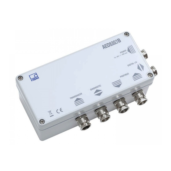
Profibus connections, slide switches for bus disconnection and termination resistor connection and the voltage sta- bilizer. The connection cables exit the casing via PG glands on the side. Fig. 2-1: Mechanical construction AED9301B (without amplifier) AED9301B... -
Page 10: Electrical Connections
When making the connections, please ensure that the wires of the cable do not protrude beyond the connection terminals (risk that loops may form). Please make sure that the cable shielding is properly connected to the PG gland (see the AED9301B cable connec- tion via PG glands section). - Page 11 = 80...4000 . With a transducer resistance of >1000 , increased noise (measurement ripple) must be taken into account. The bridges are supplied with power in the AED9301B basic device at 5 V The 6-wire connection avoids the effect of a long cable on the measured value. When sev- eral transducers and a junction box are used, the 6-wire circuitry is routed to the junction box.
- Page 12 Cable shield Fig. 3.1-3: Transducer connection in 4-wire circuitry via a 6-core cable extension When connecting several transducers, it is advisable to use an HBM junction box VKKx. In general, the feed lines running to the AED should be shielded cables.
- Page 13 Equivalent circuit of the bridge with bridge resistance R and supply lines with line resistances R and R The voltage drop over the bridge feeder cables can be determined from bridge resistance RB, cable length l, cable cross-section A and the bridge excitation voltage: AED9301B...
- Page 14 This change in bridge excitation voltage directly at the transducer changes the measurement signal of the bridge by 2 % (= 100 % (1 – 3.53 V / 3.6 V)). This typical calculation shows that if long cables are involved, only 6-wire circuitry should be used. AED9301B...
-
Page 15: Connecting The Supply Voltage
Connecting the supply voltage Connecting the supply voltage The power supply must meet the following requirements: AED9301B DC voltage +18 V...+30 V Current consumption 200 mA + current of control outputs OUT1...4 (at 80 bridge resistance and 24 V power) Calculating total current consumption (at 80 ... -
Page 16: Profibus Connection
Profibus DP is fully standardized to IEC61158 / EN50170 for universal automation, so there is no difficulty in connecting components that conform to the standard. In the case of the AED9301B, this is a Profibus DP Slave in accordance with DIN19245-3. It provides a simple and quickly implemented option for connecting electromechanical meas- urement sensors to automation systems such as SIEMENS SIMATIC S7 or to PCs. - Page 17 Profibus error (red) When there is a bus error, LED 4 shows red and stays on as long as the error persists. Possible causes: - Incorrect wiring (A and B may be transposed) - Profibus Master not (yet) working AED9301B...
-
Page 18: Connecting Digital Inputs/Outputs
GSD file is described in the aed_help_e, AD9301A; “Description of the Profibus commu- nication”. Also the linking the bus via a PC and the HBM Profibus Panel program. The Profibus can be separated from the AED for diagnostic purposes (bus link (S3) to “off”). - Page 19 = low, activation = low-high-low-Puls Start dosing (duration 20 ms) Unused inputs remain open. If the input circuit is also supplied via U , the ground of the inputs and the ground of the U must be connected. AED9301B...
- Page 20 Low (H-side switches deactivated) Logic level: OUT inaktiv voltage is High (H-side switches activated) OUT aktiv The functions of the digital inputs and outputs differ in accordance with the type of measuring amplifier used (basic, plus) AED9301B...
- Page 21 LIV2 deactivated: control OUT2 via POR command LIV1 deactivated: limit value LIV1 controls output OUT1 LIV2 deactivated: limit value LIV2 controls output OUT2 LIV3 deactivated: limit value LIV3 controls output OUT3 LIV4 deactivated: limit value LIV4 controls output OUT4 AED9301B...
- Page 22 OUT4 Tolerance+ overrun Alarm Outside Tolerance for emptying time = 0 (EPT) OUT3 ready signal is after actual value determination, for emptying time > 0 (EPT) OUT3 emptying control is over set time AED9301B...
-
Page 23: Connecting The Diagnostic Bus
The interfaces setting of the bus is defined and cannot be changed (38400 bit/s, 8E1). External bus termination resistances are not necessary for this bus. The HBM interface converter can be used to connect the RS485 bus to an (RS232) COM port of the PC. - Page 24 The diagnostic functions can be executed using the HBM AED_Panel32 program (as from Version V3.0.0). The HBM display unit DWS2103 can be connected with this interface. Than all implemented functions and parameters are accessible. This is independent from the main communication channel.
-
Page 25: Aed9301B Cable Connection Via
PG gland. On the other side, connect the screen extensively to ground (housing). If there are vast differences between the ground potential of the AED9301B and its partner device, a potential equalization line must be pro- vided in addition. -
Page 26: Index
...............................14, 16 cable connection..............................16 cable connection - digital inputs........................16 cable connection supply voltage cable connection AED9301B ........................13, 23 cable length ................................. 15 connecting the diagnostic bus ..........................21 control input ................................. 16 control inputs – logic level..........................16 control outputs .............................. - Page 27 Index LED ..................................15 light-emitting diodes ............................. 15 load cell connection ............................. 11 logic level................................16 Profibus ............................4, 6, 14, 15, 16 Profibus address .............................. 15 supply voltage supply voltage AED9301B ...........................13, 23 transducer connection............................8 AED9101B...
- Page 28 All details describe our products in general form only. They are not to be understood as express warranty Postfach 100151 D-64201 Darmstadt and do not constitute any liability whatsoever. Im Tiefen See 45 D-64293 Darmstadt Tel.: +49/6151/803-0 Fax: +49/6151/8039100 I1694-2.0 en E-mail: support@hbm.com · www.hbm.com...
Need help?
Do you have a question about the AED9301B and is the answer not in the manual?
Questions and answers