
Subscribe to Our Youtube Channel
Related Manuals for HBM AED9101D


Summary of Contents for HBM AED9101D
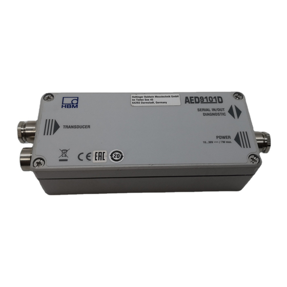
- Page 1 Operating Manual English Digital Transducer Electronics AED9101D Basic device for AD103C with RS‐232, RS‐422, RS‐485...
-
Page 2: Table Of Contents
AED9101D Safety instructions ........ -
Page 3: Safety Instructions
AED9101D Safety instructions Appropriate use The device is to be used exclusively for measurement tasks and directly related control tasks within the applica- tion limits detailed in the specifications. Use for any pur- pose other than the above is deemed to be non-desig- nated use. - Page 4 In particular, any repair or solder- ing work on motherboards (replacement of compon- ents) is prohibited. When exchanging complete mod- ules, use only original parts from HBM. S The device is delivered from the factory with a fixed hardware and software configuration. Changes can only be made within the possibilities documented in the manuals.
- Page 5 AED9101D This includes people who meet at least one of the three following requirements: S Knowledge of the safety concepts of measurement and automation technology is a requirement and as project personnel, they must be familiar with these concepts. S As measurement or automation plant operating per- sonnel, they have been instructed how to handle the machinery.
- Page 6 AED9101D signal transmission do not cause undefined states or loss of data in the automation device. S After making settings and carrying out activities that are password-protected, ensure that any controls that may be connected remain in a safe condition until the switching performance of the device has been tested.
-
Page 7: Markings Used
The CE mark enables the manufacturer to guarantee that the product complies with the requirements of the relev- ant EC directives (the Declaration of Conformity can be found on the HBM website (www.hbm.com) under HBM- doc). Statutory waste disposal mark... - Page 8 AED9101D Symbol Meaning This marking indicates application tips or other information that is useful to you. Italics are used to emphasize and highlight text and Emphasis identify references to sections, diagrams, or external See … documents and files. Bold italics indicate inputs or commands sent to the STP;...
-
Page 9: Introduction
Introduction Scope of supply S Quick start guide S AED9101D (basic device) A PDF of this operating manual is available on the HBM website (www.hbm.com) under HBMdoc at Digital weigh ing electronics. Application AED9101D digital transducer electronics are part of the... - Page 10 The AED_Panel32 PC software is available to facilitate parameter settings, to display dynamic measurement signals and for comprehensive analysis of the system. Download your (free) software from the HBM website, at Digital weighing electronics: www.hbm.com/HBM Soft- ware. The AED commands are described in the online Help of this program.
-
Page 11: Design And Function
AED9101D Design and function The AED basic device extends the functionality of AD amplifier boards and provides: S mechanical protection (IP65) S the voltage supply for the amplifier board and trans- ducer excitation S bridge excitation for transducers with a total bridge resistance of 40 to 4000 ... - Page 12 AED9101D Transducer connection Interface settings RS‐485 bus termination AD10x amplifier connection Terminals for interface, supply voltage, trigger input and diagnostic bus Fig. 4.1 Mechanical construction I3563-1.0 en...
-
Page 13: Mechanical Installation
AED9101D Mechanical installation Conditions on site S Protect the device from direct contact with water. S Protect the device from moisture and weather such as rain or snow. The protection class of the device is IP65 (DIN EN 60529). S Do not expose the device to direct sunlight... -
Page 14: Electrical Connection
(risk of interference coupling). Please also make sure that the cable shield is properly connected to the PG gland, see Section 6.7 on page 28. A connection diagram is attached inside the lid of the each AED9101D basic device. I3563-1.0 en... -
Page 15: Transducer Connection
4000 . With a transducer resistance of more than 1000 , increased noise (measurement ripple) is to be expected. Transducer excitation is supplied in the AED9101D basic device at 5 V (bridge excitation voltage). When connecting several transducers, use the HBM VKKx junction box. -
Page 16: Four-Wire Circuit
Cable braid Housing Fig. 6.2 Transducer connections for a sixwire configuration (HBM color and connection coding) The six-wire connection eliminates the effect of cable resistance. If you are using several transducers, make the six-wire connection up to the junction box. - Page 17 AED9101D AED9101D BU (3) GN (3') RD (4) HBM color code: WH (1) BU = blue GN = green GY (2') RD = red WH = white BK (2) GY = gray BK = black Fig. 6.3 Connecting transducers with a fourwire...
-
Page 18: Connecting The Supply Voltage
The actual current consumption depends on the level of the voltage supply and falls if the supply voltage is higher. AED9101D +10...30 V HBM color code: RD = red WH = white Fig. 6.5 Connecting the voltage supply The voltage supply leads can be routed together with the interface leads in one cable, or you can use a separate cable. -
Page 19: Connection To A Pc
28). The voltage supply can also be routed via this cable, which means that a 5 or 6-wire, shielded cable is required, depending on the interface. EMC reasons make it an advantage to use a double-shielded cable, such as HBM type 4-3301.0071, at 3 2 0.14 m I3563-1.0 en... - Page 20 AED9101D Interface configuration, DIP switches S1 to S6 Bus termination Fig. 6.7 DIP switch positions for the interface configuration The interface cable shield must not be connected to GND or to the supply ground, but to the housing of the AED (see Section 6.8 on page 29).
-
Page 21: Connection Via Rs-232
AED9101D 6.3.1 Connection via RS‐232 The RS-232 interface allows an AED to be directly con- nected to a PC. The length of the cable is limited to 15 m, and only one AED can ever be connected to each interface on the PC. -
Page 22: Connection Via Rs-422
STP;. The interface converter must be set to 2-wire operation. In both cases, an interface converter is required at the PC's (RS-232) COM port (HBM interface converter: 1-SC232/422B). The advantage of this interface is that I3563-1.0 en... -
Page 23: Using Several Aeds (Bus Mode With Rs-485)
RA = R- RB = R+ Fig. 6.9 Connecting an AED (RS422 or RS4854wire) to a PC via the HBM interface converter; also see Fig. 6.6 on page 19 Using several AEDs (bus mode with RS‐485) Up to 89 AEDs can be connected via the RS‐485 inter- face to a common bus line, the total length of which can I3563-1.0 en... - Page 24 (bus termination), which in Fig. 6.10 is the PC and AED 89. The HBM interface converter already contains these bus termination resistors (cannot be switched off); in the AED (89 in the example), you must slide the DIP switch for bus termination to the right (ON) (see Fig.
-
Page 25: Connecting The Diagnostic Bus
AED9101D termination with commands STR1;TDD1; in the relevant AED. If the DIP switch for bus termination is set to OFF, the commands will not take effect, i.e. bus termination will remain switched off! Important Termination resistors must only be activated at the end points of the interface cable. - Page 26 RS-485 interface, see Section 6.3.3, starting on page 22. You can also use the HBM interface converter for con- necting the RS-485 diagnostic bus to a PC COM port (RS-232).
-
Page 27: Trigger Input
AED9101D Trigger input When using AD103C, you can connect an external sensor (light barrier, contact, etc.), to the trigger input, to enable you to use the trigger measurement function (see AD103C operating manual). Use command TRC to activ- ate the input as an external trigger. Leave the input unas- signed, if you do not need it. -
Page 28: Cable Connection Via The
AED9101D Cable connection via the PG gland The connection between AED9101D and other devices can only be made via a connecting cable with a shield grounded on both sides and metal connectors (or a metalized connector housing). Bring the screen extens- ively into contact on both sides at the PG gland and at the connector housing. -
Page 29: Ground (Gnd) And Shield Wiring
AED9101D Shorten the cable shield Remove the outer cable and bare the stranded sheath to the required wires length of wire L Strip the insulation from the cable termination and tin it Push the screwed cable gland with the gasket... - Page 30 AED9101D An example of cable shield and supply voltage wiring is shown in Fig. 6.14. Grounding/ Assignment at the PC power supply housing (RS‐232): AED with 9‐pin socket 25‐pin socket RS‐232 (solder view) (solder view) Shield grounding/housing Fig. 6.14 Connection of an AED to the supply voltage and a computer via the RS-232 interface I3563-1.0 en...
-
Page 31: Selling On, Waste Disposal And Environmental Protection
Packaging The original packaging of HBM devices is made from recyclable material and can be sent for recycling. For ecological reasons, empty packaging should not be returned to us. -
Page 33: Index
AED9101D Index Computer connection, 19 Connection to a computer, 19 4-wire configuration, 16, 17 Diagnostic bus, 25 6-wire connection, 16 Diagnostic bus connection, 25 a basic box, 11 Electrical connections, 14 Basic device, 11 Interface, 19 Interface converter, 22 Bus line, 23... - Page 34 AED9101D RS232, 13, 19 RS422, 13, 19 RS485 quiescent level, 23 RS485 with 2-wire, 19 RS485 with 4-wire, 19 Safety instructions, 3 Serial interface, 13 RS232, 9, 11, 19 RS422, 9, 11, 19 RS485, 11, 19 Supply voltage, AED9101C supply...
- Page 36 They are not to be understood as a guarantee of quality or durability. Hottinger Baldwin Messtechnik GmbH Im Tiefen See 45 · 64293 Darmstadt · Germany Tel. +49 6151 803-0 · Fax: +49 6151 803-9100 Email: info@hbm.com · www.hbm.com measure and predict with confidence...
Need help?
Do you have a question about the AED9101D and is the answer not in the manual?
Questions and answers