Table of Contents

Related Manuals for Ebyte E820-AIO


Summary of Contents for Ebyte E820-AIO
- Page 1 Data Acquisition Module E820-AIO User Manual This manual may be modified based on product upgrade, please refer to the latest version. All rights to interpret and modify this manual belong to Chengdu Ebyte Electronic Technology Co., Ltd.
- Page 2 E820-AIO is the analog signal collection product designed by Ebyte. With RS485 communication network, E820-AIO transmits the analog signal of scattered field data point via AD transformation to master or control remote home site via the PC. Built-in watch dog (0.2s reset), the system won’t be halted easily.
-
Page 3: Electrical Parameters
1. Electrical Parameters 1.1 E820-DTU(AI-485-4-5) Parameter Name Parameter value Description Size 82 * 84 *25mm Pressing line interface is not included. Average weight 150g Pressing line interface is not included. Input signal type 0—20mA/0-5V Analog signal input range. Acquisition channel 4 channel input 4 channel current collection and all differential voltage acquisition. - Page 4 1.4 FAQ Questions Description Change baud rate When using the upper computer, users need to close the upper computer first and reopen after changing the baud rate. Forget the device address Users can use 03 command to read FF monitoring. 1.5 Notice Notice Description...
-
Page 5: Function Description
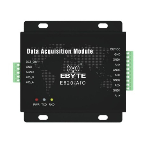
2. Function Description 2.1 Pin definition 2.1.1 E820-DTU(AI-485-4-5)... - Page 6 Definition Function Description DC-IN Pressing line power input positive Power input, range: DC10-28V. 12V, and 24V are recommended. Pressing line power input negative Power supply GND. When communicating with RS485, the DTU won’t be used, while when AGND Communication common ground communicating with RS232, it will be grounded.
- Page 7 2.1.2 E820-DTU(II-485-4-20)...
- Page 8 Definition Function Description DC8-28V Pressing line power input positive Power input, range: DC10-28V. 12V, and 24V are recommended. Pressing line power input negative Power supply AI-. When communicating with RS485, the DTU won’t be used, while when AAI- Communication common ground communicating with RS232, it will be grounded.
-
Page 9: Modbus Address Table
3. Register configuration table 3.1 ModBus address table 40001—40012、40017—40028、40042—40049 is not used in this device. ModBus register address table Address Byte variable names Type Description 40013 AI1 input Read only 40014 AI2 input Read only Unit 0.001mA/0.001V 40015 AI3 input Read only 40016 AI4 input... -
Page 10: Instruction Format
4. Instruction format 4.1 Input“03”to read the command of single register Users input”03” to read the command of register value. Below is the command to read the value of baud rate: 00 21 00 01 D4 00 ModBus Address To read command To read the address of register To read the length of register CRC parity code... -
Page 11: Important Statement
5.1.MoBusCRC16 calculator Ebyte will provide the MoBusCRC16 calculator for your convenience, which will automatically add the CRC16 parity check code after the input data. Please pay attention to the format, if it’s less than f, then should add 0 in the front, such as 01, 06, and each digit should followed by a blank.