Table of Contents
Advertisement
Quick Links
Advertisement
Table of Contents

Related Manuals for Ebyte E831-RTU(8080T-485)


Summary of Contents for Ebyte E831-RTU(8080T-485)
- Page 1 E831-RTU(8080T-485) Usermanual v1.0 This manual may change as the product continues to improve, please refer to the latest version of the manual All rights to interpret and modify this Manual belong to Chengdu Ebyte Electronic Technology Co., Ltd...
-
Page 2: Table Of Contents
CONTENTS Functional features..........................3 1. Quick start............................3 1.1. Port connection........................... 4 1.2. Simple use...........................6 Note: Do not select automatic refresh when reading or writing parameters........8 2. Product introduction..........................9 2.1. Basic parameters.........................9 2.2. Size, Interface description......................10 2.3. Command reset description...................... 13 3. -
Page 3: Functional Features
Functional features Support 8 digital isolated inputs,default dry contact; 8 digital outputs (NPN transistor electrode open collector output)adopts Modbus RTU protocol data processing; Support command reset. After sending AT + RESTORE \ r \ n instruction to 485 serial port within ... -
Page 4: Port Connection
1.1. Port connection 1.1.1. RS485 Connection Note: When transmitting high-frequency signals on the 485 bus, the signal wavelength is shorter than the transmission line. The signal will form reflected waves at the end of the transmission line and interfere with the original signal. Therefore, a terminating resistor must be added at the end of the transmission line so that the signal does not reflect after reaching the end of the transmission line. - Page 5 1.1.2. Digital input connection 1.1.3. Digital output(NPN transistor collector open circuit output) connection...
-
Page 6: Simple Use
1.2. Simple use Wiring: The computer is connected to E831-RTU (8080T-485) via USB to RS485. Power supply: E831-RTU (8080T-485) working voltage is DC 8 ~ 28V, 12V or 24V is recommended. 1.2.1. RS485 bus control Select the corresponding model and port, and click Search to search for the device. When the device is searched, click "Stop"... - Page 7 At this time, you can see the device address of the current device. Click on read parameters or write parameters to read parameters and configure parameters.
-
Page 8: Note: Do Not Select Automatic Refresh When Reading Or Writing Parameters
Note that when configuring or reading parameters, do not tick the Auto Refresh. Tick Auto Refresh to read and configure the input and output ports. Note: Do not select automatic refresh when reading or writing parameters. Select automatic refresh after configuration or reading is completed, otherwise the parameter writing or reading may not be successful. -
Page 9: Product Introduction
2. Product introduction E831-RTU (8080T-485) is an IO product that supports 8 digital inputs (default dry contact) and 8 digital outputs (NPN transistor open collector output). It supports Modbus RTU protocol. The product is easy to use, allowing users to quickly and easily integrate into their systems 2.1. -
Page 10: Size, Interface Description
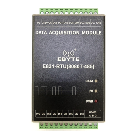
2.2. Size, Interface description... - Page 11 Ports and other Function Description definitions Connect with the earth Connect with the earth Crimped power input negative Power supply reference ground Crimped power input positive Power input,DC 8V~28V, 12V/24V recommended Digital output channel 8 NPN transistor open collector output channel 8 Digital output channel 7 NPN transistor open collector output channel 7...
- Page 12 Digital output channel 4 NPN transistor open collector output channel 4 Digital output channel 3 NPN transistor open collector output channel 3 Digital output channel 2 NPN transistor open collector output channel 2 Digital output channel 1 NPN transistor open collector output channel 1 Signal reference ground Signal reference ground...
-
Page 13: Command Reset Description
2.3. Command reset description Within 3 seconds after power-on, send a command to 485 serial port: AT + RESTORE \ r \ n can reset the local MODBU address, serial port baud rate, and parity parameters are the default parameters (1,9600, no parity). -
Page 14: Modbus Address Table
40051 DI3 Pulse count value Read only 0-65535 (0x0032) 40052 DI4 Pulse count value Read only 0-65535 (0x0033) 40053 DI5 Pulse count value Read only 0-65535 (0x0034) 40054 DI6 Pulse count value Read only 0-65535 (0x0035) 40055 DI7 Pulse count value Read only 0-65535 (0x0036) -
Page 15: Rs485 Serial Port Parity Digit Code Value Table
4800 9600 3(Default) 19200 38400 57600 115200 3.4. RS485 Serial port parity digit code value table Parity digit code value table 0 (Default) No parity Even parity Odd parity 3.5. Configure parameters through host Select the “Parameter Setting” column to read and write parameters. For specific functions, refer to product function introduction below. -
Page 16: Product Features
4. Product features 4.1. Mode selection The device supports 3 types of pulse counting methods, rising edge counting, falling edge counting and level counting methods, see the pulse counting and clearing section below. 4.2. IO Basic function 4.2.1. Switch value DO output 4.2.1.1. - Page 17 Function code:01,Read coil status Address range : 00017(0x0010)~00023(0x0017) Example: Read 8 digital output status. Assuming the return value is 03, the corresponding binary bit is 0000 0011, which means that DO1 and DO2 are on. The 8 bits represent digital output status, which are DO8, DO7, DO6, DO5, DO4, DO3, DO2, DO1 in order.
- Page 18 Modbus RTU protocol write digital output: 00 11 00 02 62 95 Transmis Switch Write Bytes Device ModBus Function Write sion value switch value numbe Address code value parity code address numbers 00 11 00 02 84 0F Receivin Switch Device ModBus Function value...
-
Page 19: Io Features
4.3. IO Features 4.3.1. Pulse counting and counting clear The device supports 3 kinds of pulse counting methods, rising edge counting, falling edge counting, and level counting. This value can be set by writing the corresponding value to the (0x0053) register. Writing 0 represents rising edge counting, writing 1 represents falling edge counting, writing 2 represents level counting. - Page 20 4.3.1.2.Manual clear pulse count value Function code: 06, Write holding register Address range: 40065 (0x0040) Description: The lower four bits of the register value represent the counts of DI6, DI5, DI4, DI3, DI2 and DI1 respectively. Writing "1" means clearing the count and restarting the pulse count. Example: Clear the pulse count value of DI2 and DI4, and keep the pulse count value of DI1 and DI3.
-
Page 21: Important Statement
0000 1010, that is, 0xa0, "1" is the closed state, and "0" is open status. Important statement Ebyte reserves the right of final interpretation and modification of all contents in this manual. As the hardware and software of the product are continuously improved, this manual may be ... -
Page 22: Revision History
Revision history Version Data Description Issued by Initial version 2019/8/19 Format adjustment Linson About us Sales hotline: 4000-330-990 Tel: 028-61399028 Support: support@cdebyte.com Website: www.ebyte.com Address: Innovation Center B333~D347, 4# XI-XIN road,High-tech district (west), Chengdu, Sichuan, China...