
Related Manuals for AmTryke 1416


Summary of Contents for AmTryke 1416
- Page 1 Instruction Manual 1416, 1420, 1420-XL (Part #s: 50-FC-1416, 50-FC-1420, 50-FC-1420-XL) Includes Rear Steering Kit Instructions for 1416, 1420, and 1420-XL (Part #s: 30-50-1516; 30-50-1520; 30-50-1420-XL)
-
Page 2: Table Of Contents
Basket ......................22 Steering Pin ....................23 Wheel Reflectors ................... 23 Additional Assembly Instructions ..............25 Front Brake (Models 1416 and 1420) ............25 Brake Lever and Cable................25 Brake Caliper ..................... 26 Brake Adjustment ..................27 3-Speed Model (1416 and 1420) ..............27 Rear Steering Bar with Hand Brake (Models 1516 and 1520) ....... -
Page 3: About Amtrykes
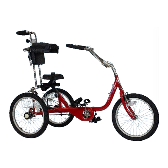
About Amtrykes ® Amtryke, LLC is fully owned and operated by National AMBUCS™ Inc, a 501c3 charity. Amtryke therapeutic tricycles are designed for people with disabilities who are unable to safely operate a traditional bicycle. Amtryke tricycles or “trykes,” can be operated by feet, hands or both feet and hands together. A wide variety of models can be adjusted to fit the needs of different riders by choosing the optimal seat, handlebars, back rest and adaptive accessories. -
Page 4: Safety
Before riding, familiarize yourself how the tryke operates — it’s steering, braking and gear shifts (if applicable). Adjust the seat, handlebars and pedals to fit the rider. See Fitting Amtryke for Rider in this manual for more information. Here are some tips about riding safety: •... - Page 5 • Riders should only be allowed to ride trykes that are the appropriate size. If you are uncertain, refer to Amtryke Sizing Chart in this manual or contact a physical therapist or occupational therapist.
-
Page 6: Brakes
Brakes If your tryke has brakes (front or coaster brakes) be careful when using the brakes. Operate the brakes gradually. If your tryke has front brakes (front caliper brake or both front caliper brake and rear disk brake) squeeze the brake lever(s) gradually until you feel brake(s) working. -
Page 7: Assembly Instructions
SECURELY TIGHTENED BEFORE USING YOUR TRYKE. Getting Started Your Amtryke is shipped in parts. Carefully remove and lay out all parts from the carton so that you don’t scratch or lose any parts or pieces. Check that you have all the necessary parts. If any parts are missing, please call us at 800-838- 1845 for assistance. - Page 8 Seat post bracket Rear frame Chain Pedal Back wheel guard crank Front Pedal Pedal leveler wheel Frame Rear steering control pulley knob arm (1516, 1520) 1416, 1420, 1516 & 1520 parts Brake noodle (1416, 1420 Hardware...
-
Page 9: Frames
• Quick release wrench (incl.) • #2 Phillips head screwdriver Frames Start assembling your Amtryke by first attaching the main and rear frames together: Step 1: Slide the main frame onto the Step 2: Insert the safety pin through both rear frame. -
Page 10: Wheels
Rear Steering 1500 Kit - optional Available on ProSeries 1416, 1420, and 1420-XL Amtrykes (Part #: 30-50-1516; 30-50-1520; 30-50-1420-XL) Please skip this section if not installing rear steering option 1. Install Rear Disc Brake Rotor and Disc Caliper on the left rear wheel axle of the main frame. - Page 11 2. Install the 3mm set screw through rotor using a 3mm Allen wrench, tighten securely. 3. Install rear wheels (do not use the 22mm silver spacer tube on the left side axle if you are installing the rear steering kit). 4.
- Page 12 a.) TIP: Flip the bike upside down. It is easier to install the disc brake caliper and steering control arm support plate from the bottom. b.) Insure brake pads slide smoothly over brake rotor or disk. c.) Put in black bolts with 5mm Allen wrench. Hint: tighten the shorter rear bolt first as it will touch the bracket.
- Page 13 7. Install Red Rear Steering Assembly. a.) Loosen the two (2) screws holding the black basket plate to the bottom rear of the main frame first. Just loosen, do not remove. b.) It is important that all the screws and bolts be loosely installed at first. This will allow you to line up all the holes and get the screws started easily.
- Page 14 side (with tryke upside down) of the red bracket must rest between tryke frame and black basket plate. g.) Install two (2) of the 15mm hex head screws but do not tighten yet. h.) Flip tryke over so it is now right side up. i.) Now you can install the basket and the red rear steering assembly.
- Page 15 b.) Screw red steering control arm into the bushing on the black steering linkage at rear of tryke and tighten all the way. Then, unscrew it one rotation to allow adjustments. c.) Note: This is the straight end. The curved end of the red linkage bar goes at the front and attaches to the front fork.
- Page 16 d.) Important Step: Attach the red steering control arm to the silver steering control arm support plate. The Allen screw is already installed on the steering control arm support plate inside a plastic bushing. Use the 5mm Allen wrench to fully tighten into the steering control arm. e.) Flip tryke right side up.
- Page 17 9. Install Rear Steering Bar a.) Note: Very important—the steering bar must be inserted fully into the cinch collar—the minimum insertion lines must be down inside the collar. If not installed correctly, you risk breaking the steering bar. b.) Once the steering bar is fully inserted—align with front wheel for straight ahead position—then tighten the two 5mm Allen screws on the cinch collar.
- Page 18 Step 1: Remove nuts and washers from Step 2: Replace washers and nuts on both both sides of the rear axle and slide back sides. Use a 22 mm socket or adjustable wheels onto the axle. wrench to tighten. CAUTION: DO NOT OVER TIGHTEN NUTS;...
-
Page 19: Parking Brake
Parking Brake Parking brake is used to help transition rider on/off the tryke safely and easily. To install it: 1. Remove the two Allen bolts from the brake’s extension tube. 2. Place the extension tube over the right rear axle so that the handle is pointing toward the front of tryke. -
Page 20: Seat
DO NOT EXCEED THE MAX. HEIGHT LINE Hash marks Front fork tube Handlebar stem When the stem is securely tightened, remove the two 6 mm Allen bolts from the handlebar clamp (see image below). Insert the handlebar with the quick release levers oriented up and replace the handlebar clamp. - Page 21 1. Unscrew the two levers Seat (counterclockwise) from the post clamping plate, place the seat post brack bracket onto the frame and the clamping plate onto the bottom of the frame with the two levers going through the plate. 2. Screw (clockwise) to secure. Clamping plate Levers Seat post bracket (Red)
- Page 22 5. Insert lateral support T-bars into the seat back so that quick release levers are facing outward and behind the seat post. 6. Insert the lateral supports into the T-bars and tighten the levers. NOTE: Lateral supports are grooved on the bottom and slide into supports.
-
Page 23: Pedals
Pedals TIP: Pedals and pedal cranks are labeled “R” (right) and “L” (left). Pedals are mounted onto the pedal cranks. The right pedal tightens clockwise and the left counterclockwise. Hand thread until you are certain that they are threaded properly and then use a 15 mm wrench to tighten securely. -
Page 24: Pedal Leveler Pulley
Pedal Leveler Pulley Install the pedal leveler pulley into the front hole of the black basket plate on the rear frame. Insert the pedal leveler cord through each pedal and tie a knot in one end of the cord to hold in place. Pedal leveler pulley Pedal leveler cord Basket... -
Page 25: Steering Pin
Phillips Phillips head screws head screws Basket Basket bracket Allen brace and Allen bolts bolts Basket assembly Steering Pin If needed, insert the steering pin into the front fork tube from the side. Attach the adhesive hook strip to the frame to keep the pin secure from loss. - Page 26 This is the end of basic assembly instructions for all models in this manual. See Additional Assembly Instructions for instructions that vary by model.
-
Page 27: Additional Assembly Instructions
Select models also feature a front brake and are available as a 3-speed model. Refer to following instructions on how to install these additional parts. Front Brake (Models 1416, 1420, 1420-XL) The front brake caliper is already installed but you need to install a brake lever onto the handlebar and connect the brake cable to it (the cable is already attached to the frame) and attach the cable to the brake caliper. -
Page 28: Brake Caliper
Cable barrel Step 3: Insert the cable barrel into the Step 4: Slide the cable through the slots of cable barrel arm. the ferrule and locking nut, then turn the locking nut and ferrule 180 degrees from each other. Brake Caliper To install the cable to the brake caliper, follow these instructions: 1. -
Page 29: Brake Adjustment
3-Speed Model (1416 and 1420) Models 1416 and 1420 are also available as a 3-speed version, which is suitable for higher functioning children and adults. This version features a 3-speed internal hub and coaster brakes. - Page 30 Combination shift control and hand Shifter pin brake lever NOTE: The hand brake lever can be removed from the shift control and mounted on the handlebar. TOOLS REQUIRED: • 5 mm Allen wrench To install the 3-speed shift mechanism, follow the steps below: 1.
-
Page 31: Rear Steering Bar With Hand Brake (Models 1516 And 1520)
Step 2 3. Install the combination shift control and brake lever on the loop handlebar. Use a 5 mm Allen wrench to tighten. NOTE: The shift control can also be mounted on the handlebar or the parking brake stem. Step 3 Shift control mounted on handlebar Shift control mounted on parking brake Rear Steering Bar with Hand Brake... - Page 32 The hand brake lever is preinstalled to the rear steering bar. Attach the hand brake cable to it. Follow these steps: Cable barrel arm Step 1: Turn the Ferrule so that the Step 2: Pull in on the lever and pull out slot in it and the locking nut align.
- Page 33 Bolt Step 5: Feed cable through eyelets on the Step 6: Loosen a 5 mm cable securing steering bar. bolt on the rear disc brake. Step 7: Feed the cable through the eyelet on the rear disc brake and then into the cable securing bolt.
-
Page 34: Fitting Amtryke For Rider
Fitting Amtryke for Rider The ProSeries models 1416, 1420, and 1420-XL can be adapted to different types of riders. See the information below for quick reference on rider size requirements: 1416 1420 and 1420-XL* Rider’s height: Max. 60 inches Rider’s height: Max. 72 inches 76*... -
Page 35: Optional Accessories
Optional Accessories Most Amtryke models can be adapted with a variety of seating options and accessories, so that most riders can feel safe and secure. See the table below for accessories available for 1416 and 1420: OPTIONAL ACCESSORIES Bucket seat (1416) -
Page 36: Maintenance
Maintenance Maintenance is important to help keep your Amtryke in good working order for years to come. This section includes some general maintenance tips. Wheels and Tires Wobbly wheels cut braking power, so keep all wheels running true. Wheels can lose alignment over time when spokes stretch. -
Page 37: Maintenance Schedule
Maintenance Schedule Follow this maintenance schedule to keep your Amtryke in safe operating condition. MAINTENANCE SCHEDULE PART TO DO LIST WHEN All handlebar bolts Check tightness Every 4 months Brake cables Check for slack, frayed cable Every 6 months Brake arms... -
Page 38: Warranty
Amtryke at no charge. This warranty does not include dealer service charges for parts replacement or shipping charges to or from Amtryke. FRAME: All Amtryke frames and forks are guaranteed to be free from defects in materials and workmanship for a period of three years from the date of original purchase. -
Page 39: Donations
For parents and families, the use of Amtryke fulfills the need of every child to have a bike. All children deserve a chance to have a bike just like their siblings and friends. -
Page 40: Returns And Refunds
Returns and Refunds No goods may be returned for credit without prior authorization from Amtryke and items must be sent back within 30 days. Amtryke will not be responsible for errors on size or other specifications when you order by telephone.
Need help?
Do you have a question about the 1416 and is the answer not in the manual?
Questions and answers