
Related Manuals for Atlas Copco RT


Summary of Contents for Atlas Copco RT
-
Page 1: User Guide For Rt Hydraulic Torque Wrench Systems
USER MANUAL Printed Matter No. 9839161901 RT square drive Hydraulic torque wrench system. -
Page 2: Table Of Contents
CONTENTS USER GUIDE FOR RT HYDRAULIC TORQUE WRENCH SYSTEMS ............1 WORKING PRESSURE .........................3 HYDRAULIC CONNECTIONS .......................3 ELECTRICAL CONNECTIONS ......................3 AIR CONNECTIONS ..........................3 GENERAL SETUP ..........................4 CONNECTING THE SYSTEM........................4 OPERATING THE ATLAS COPCO® RT SERIES SQUARE DRIVE ...........4 SETTING TORQUE ..........................5 SETTING WORKING PRESSURE ON THE PUMP ................5... -
Page 3: Working Pressure
WORKING PRESSURE The tool's maximum Working Pressure is 10,000 PSI (700 bar). Make sure that all hydraulic equipment (pumps, hoses, couplers) used with this tool are rated for 10,000 psi (700 bar) working Pressure. Review the documentation for the hydraulic pump in use to ensure pressure does not exceed 10,000 psi. HYDRAULIC CONNECTIONS Our hydraulic pumps are equipped with a zero-pressure relief valve. -
Page 4: 3:1 General Setup
CONNECTING THE SYSTEM The Atlas Copco hydraulic torque wrench and the power pack are connected by a 10,000 PSI (700 bar) operating pressure twinline hose assembly. The safety ratio of the Atlas Copco Hydraulic Hose is 4/1. On each twin hydraulic hose, one line must be MALE-MALE and the other line must be FEMALE-FEMALE in order to assure a correct interaction between Pump and Machine. -
Page 5: 3:4 Setting Torque
The reaction arm for all RT Monobloc Housing is splined to slide over the rear (cylinder) portion of the tool. In operation, the reaction arm must be fully engaged and secured by inserting the spring loaded reaction arm lever at the base of the housing ( End Cap ). Ensure the reaction is fully engaged prior to operation. -
Page 6: 3:7 Operating The Torque Machine
Should the tool "lock-on" after the final cycle, push down on the remote control button once more (to build pressure) and, while maintaining this pressure, pull back on the external disengagement lever (RT) or reaction Pawl (RTX). Releasing the remote control while continuing to hold back on the pawl lever/reaction pawl will allow the tool to be removed easily. -
Page 7: Setting Torque
SETTING TORQUE All Atlas Copco power packs operate at a pressure range from 500 to 10,000 PSI and are fully adjustable. They have been engineered and designed for portability and high flow for increased speed. Before using your Atlas Copco power pack, check the following points. -
Page 8: Operation
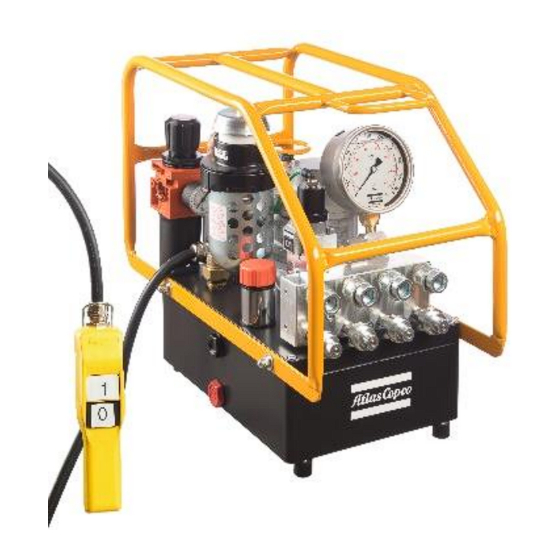
OPERATION Before starting your electric Panther Pump, connect your hydraulic hoses to both the pump and torque wrench. To start the pump, press briefly the white button on the remote control. This will start your pump and place it in the retract position push the white switch to advance and release. NOTE: Read the section labelled OPERATION and SETTING TORQUE prior to installing the torque wrench onto the application Your Panther hydraulic pump has been designed with an auto shut off system. -
Page 9: Trouble Shooting Hydraulic Torque Wrench
Air Valve: This valve should be checked twice a year. Armature: (Electric Unit) Check yearly. Pumping unit: The pump should be overhauled every 2 years. This can be done by Atlas Copco or by a qualified hydraulic service centre. -
Page 10: Troubleshooting Routines
Male to Female and Female to Male. This will cause the system to operate backwards per Test #5 above. If you hose isn’t long enough, connect 3 hoses together, move your pump or call Atlas Copco for a longer hose assembly. - Page 11 1. Run test #5. Replumb system as necessary. 2. Multiple hoses in even numbers. 2. As plumbed, Atlas Copco hoses may only be joined together in odd numbers ONLY if it is necessary to use 2, 4, 6 hoses-make an adapter from spare high pressure couplings and nipples.
- Page 12 SYMPTOM PROBABLE CAUSE REQUIRED ACTION 4. Tools seals are blown. Pump will not build 1. Air Electric supply is low. Check air pressure or voltage. pressure. 2. Defective relief or regulator valve. Replace valve. SHOP JOB. 3. Low oil or clogged filter. Fill reservoir and clean filter.
- Page 13 SYMPTOM PROBABLE CAUSE REQUIRED ACTION Motor doesn’t run Check fuse 16 a Part# 10064 1. Change fuse 16 a (white - on top) Check electrical box 2. Check for disconnection Check 115v cord 3. Check for wire cut or disconnect Check plug 4.
-
Page 14: Square / Allen Drive Working Torque
DRIVE SIZE: The square or hex drive of each drive is limited in its maximum output by its material and its engagement area. Since Atlas Copco uses a specially suited alloy-steel for its drive members, the following maximum torque output can be achieved without drive failure, provided the reaction member abuts close to the same plane as the nut to be turned. - Page 15 DRIVE MAX WORKING PROBABLE DRIVE SIZE TYPE TORQUE FAILURE ft lbs ft lbs 12mm 17mm 1147 1275 19mm 1182 1602 1313 1780 22mm 1835 2486 2039 2763 24mm 2382 3228 2647 3587 27mm 3392 4596 3769 5107 32mm 5647 7652 6275 8502 36mm...
- Page 16 Atlas Copco Bolt Tightening Solutions, UK www.atlascopco.com...
Need help?
Do you have a question about the RT and is the answer not in the manual?
Questions and answers