
Related Manuals for Angekis Saber AT


Summary of Contents for Angekis Saber AT
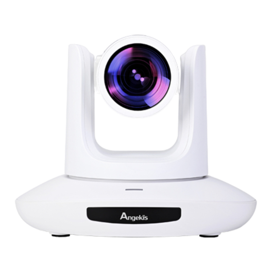
- Page 1 Autotracking PTZ Camera Saber AT User Manual V1.0 EN Please refer this document before using...
-
Page 2: Table Of Contents
Content Content......................1 Safety Guides....................2 Use Check....................4 Camera Spec....................6 Interface Description.................9 Camera Dimension...................10 IR Remote Controller................11 VISCA In(RS232 Port).................13 VISCA Protocol..................15 PELCO-D Protocol...................30 PELCO-P Protocol...................31 OSD Menu....................32 UVC Control.....................36 Web Setting....................37 View RTSP Video Via VLC...............42 VISCA Over IP..................43... -
Page 3: Safety Guides
Safety Guides ● Before operation, please fully read and follow all instructions in the manual. For your safety, always keep this manual with the camera. ● The camera power voltage is 12V DC, rated current is 2A. We suggest you use it with the original power supply adapter supplied by the factory. - Page 4 Safety Guides Attention! ▲ The video quality may be affected by the specific frequencies of the electromagnetic field. ▲ Never grasp the head of the camera, and never move the camera by hand when it is working, otherwise, the mechanism maybe damaged. Declarations:...
-
Page 5: Use Check
Use Check PACKING LIST Check all below items when open the package Camera-------------------------1PCS Power Adapter-----------------1PCS Power Cable--------------------1PCS Remote Controller---------------1PCS USB Type-C Cable--------------1PCS RS232 Cable--------------------1PCS User Manual--------------------1PCS Quick Start... - Page 6 Use Check Dial Switch Setting (at the bottom of the camera) Dial Switch (ARM) SW-1 SW-2 Instruction Upgrading mode Debugging mode Undefined Working mode Dial Switch Instruction 1 OFF Reserved Reserved 3 OFF Reserved Reserved Dial Switch SW-5 SW-6 Instruction Undefined Working mode Undefined...
-
Page 7: Camera Spec
Camera Spec ★ Adopts an advanced image processing DSP and 1/2.8 inch 2.4MP image sensor. ★ High-Definition Optical Lens: 20x optical zoom, with 60-degree field of view. ★FHD 1080P60 video output from Ethernet, while supporting H.264, H.265 encoding. ★ Supports POE+: one single Ethernet cable to get video, control, and power supply. - Page 8 Camera Spec ANG2-20FHD-AT Sensor 1/2.8” inch high quality, 2.4 MP CMOS Sensor 1920*1080P60/59.94/50/30/29.97/25/24/23.98 HDMI 1920*1080I60/59.94/50 1280*720P60/59.94/50/30/29.97/25 1920*1080P60/59.94/50/30/29.97/25/24/23.98 1920*1080I60/59.94/50 1280*720P60/59.94/50/30/29.97/25 Video Format MJPG, H.264, HEVC: 1920*1080P60; 1280*720P60; 1024*576P60; 800*448P60 NV12, YUY2: 1920*1080P5; 1280*720P15; 1024*576P25; 800*448P30 1920*1080P15~60; 1280*720P15~60; 1024*576P15~60; 640*360P30 Video Interface HDMI, SDI, RJ45, USB Type-C Audio Interface 3.5mm Line in...
- Page 9 Camera Spec Video Bit Rate 1024~61440kbps HTTP, RTSP, RTMP, ONVIF, Visca TCP, Visca UDP, Visca over IP, Visca Protocol Serial, Pelco-P, Pelco-D POE+ Supported Daisy Chain Support RS232 serial daisy chain Minimum Lux 0.01 lux White Balance Auto / Manual / ATW / Push / Indoor / Outdoor / Color Temperature Exposure Auto / Manual / Iris / Bright Focus...
-
Page 10: Interface Description
Interface Description 1. Camera Lens 6. Tripod Screw Hole 11. USB Type-C port 2. Camera Base 7. Installation Hole 12. HDMI port 3. IR Receiver Panel 8. RS232 ((IN) port 13. 3G-SDI port 4. Power Indicator Light 9. RS232 (OUT) port 14. -
Page 11: Camera Dimension
Camera Dimension... -
Page 12: Ir Remote Controller
IR Remote Controller Power Key Under Normal working mode , short press Power, key to let the camera enter standby mode; Press it again , the camera will do self-configuration and then go back to HOME position;It will go to preset position if the power on mode has been set. - Page 13 IR Remote Controller Menu Key OK: to confirm the menu selection Menu:enter/exit menu Back:Back to previous menu F+/F-: Set focus by manual, only valid under manual focus mode. T/W: Set the lens zoom rate Navigating Key: Up/Down/Left/Right Under normal working mode, use navigate key to set the pan tilt, and select values when enter OSD.
-
Page 14: Visca In(Rs232 Port
VISCA In(RS232 Port) V_IN V_OUT V_IN RS485 A(+) IR OUT B(-) VISCA IN and Mini DIN Connection VISCA IN and DB9 Connection CameraVISCA IN Windows DB-9 Camera VISCA IN Mini DIN A(+) A(+) IR OUT IR OUT B(-) B(-) - Page 15 VISCA In(RS232 Port) VISCA Network Construction: SERIAL PORT CONFIGURATION: Parameter Value Baud rate 2400/4800/9600/115200 Start bit 1bit Date bit 8bits Stop bit 1bit Check bit None...
-
Page 16: Visca Protocol
VISCA Protocol Part1 Camera Return Command Ack/Completion Message command Note z0 41 FF Returned when the command is accepted. Completion z0 51 FF Returned when the command has been executed. Error Messages command Note Returned when the command format is different or Syntax Error z0 60 02 FF when a command with illegal command parameters is... - Page 17 VISCA Protocol Command type function command t: spd 0~7 8x 0A 04 47 0t 0p 0q 0r 0s Direct with speed pqrs: Zoom Position (0(wide) ~0x4000(tele)) 8x 01 04 06 02 FF 8x 01 04 06 03 FF Combine with optical Combine Mode 8x 01 04 36 00 FF zoom control...
- Page 18 VISCA Protocol Direct 8x 01 04 43 00 00 0p 0q FF pq: R Gain (0~0xFF) Reset 8x 01 04 04 00 FF Manual Control of B 8x 01 04 04 02 FF Gain CAM_B Gain Down 8x 01 04 04 03 FF Direct 8x 01 04 44 00 00 0p 0q FF pq: B Gain (0~0xFF)
- Page 19 VISCA Protocol 8x 01 04 3D 02 FF Exposure Compensation ON/OFF 8x 01 04 3D 03 FF CAM_WDR pq: ExpComp Position Direct 8x 01 04 D3 pq FF (0~0x6) 8x 01 04 33 02 FF BackLight On CAM_Back Light(BLC) 8x 01 04 33 03 FF BackLight Off Reset 8x 01 04 02 00 FF...
- Page 20 VISCA Protocol 8x 01 06 C2 03 FF p: Freeze switch 3=OFF, CAM_Freeze Freeze 8x 01 04 75 0p FF 2=ON CAM_Preset Freeze p: Preset Freeze switch Preset Freeze Set 8x 01 04 76 0p FF 3=OFF, 2=ON CAM_Preset PT Speed qq:Preset PT Speed Preset PT Speed Set 8x 01 7E 01 0B 00 qq FF...
- Page 21 VISCA Protocol Video format 1080P60 0x00 1080P50 0x01 1080I60 0x02 1080I50 0x03 1080P30 0x04 1080P25 0x05 720P60 0x06 Video System 720P50 0x07 8x 01 06 35 00 pp FF Set(Factory) 720P30 0x08 720P25 0x09 1080P5994 0x0E 1080I5994 0x0F 1080P2997 0x10 720P5994 0x13 720P2997...
- Page 22 VISCA Protocol 8x 01 04 AB 0p 0q 0r 0s 0m 0n IP set Set ip to: pq.rs.mn.xy 0x 0y FF 8x 01 04 AC 0p 0q 0r 0s 0m 0n IP address control Mask set Set mask to: pq.rs.mn.xy 0x 0y FF 8x 01 04 AD 0p 0q 0r 0s 0m 0n Set gateway to :...
- Page 23 VISCA Protocol Contor mode: 0xpq Stream Rate Mode 8x 01 04 C3 05 0p 0q FF 0x00: CBR 0x01: VBR Menu On 8x 01 06 06 02 FF Turn on the menu Menu Off 8x 01 06 06 03 FF Turn off the menu SYS_Menu Menu Back...
- Page 24 VISCA Protocol 8x 01 06 07 00 0W W: 1: Up Right 0Y 0Y 0Y 0Y 0Z 0Z 0Z 0Z FF 0: Down Left Pan-tilt Limit Set YYYY: Pan Limit Position(TBD) 8x 01 06 07 01 0W Clear ZZZZ: Tilt Limit Position(TBD) 07 0F 0F 0F 07 0F 0F 0F FF Part3 Camera Inquiry Command Command type...
- Page 25 VISCA Protocol Command type command return note y0 50 03 FF OnePush mode y0 50 04 FF y0 50 05 FF Manual CAM_RGain Inq 8x 09 04 43 FF y0 50 00 00 0p 0q FF pq: R Gain CAM_BGain Inq 8x 09 04 44 FF y0 50 00 00 0p 0q FF pq: B Gain...
- Page 26 VISCA Protocol Command type command return note y0 50 03 FF CAM_WDR Pos Inq 8x 09 04 D3 FF y0 50 0p FF p: WDR Position CAM_Aperture Inq 8x 09 04 42 FF y0 50 00 00 0p 0q FF pq: Aperture Gain pp: Memory number CAM_Preset Exist Inq...
- Page 27 VISCA Protocol Command type command return note CAM_Flare Mode Inq 8x 09 04 B6 FF y0 50 pp FF CAM_Flare Bright Mode 8x 09 04 B7 FF y0 50 pp FF CAM_Flare Red 8x 09 04 B8 FF y0 50 pp FF CAM_Flare Green 8x 09 04 B9 FF y0 50 pp FF...
- Page 28 VISCA Protocol Command type command return note pqrs : Column(x size) mnxy: Line (y size) Mainstream Resolution y0 50 0p 0q 0r 0s 0m 0n 0x 0y only support: 8x 09 04 C2 00 FF 1920*1080 1280*720 1024*576 y0 50 0p 0q 0r 0s 0m 0n 0x 0y pqrsmnxy: bitrate Main stream Rate Inq 8x 09 04 C2 01 FF...
- Page 29 VISCA Protocol Command type command return note Contor mode:0xpp Sub Stream Rate Mode 8x 09 04 C3 05 FF y0 50 pp FF 0x00: CBR 0x01: VBR VISCA PAN TILT ABSOLUTE POSITION VALUE PAN ANGLE VISCA value TILT ANGLE VISCA value -170 0xF670 0xFE50...
- Page 30 VISCA Protocol...
-
Page 31: Pelco-D Protocol
PELCO-D Protocol Function Byte1 Byte2 Byte3 Byte4 Byte5 Byte6 Byte7 0xFF Address 0x00 0x08 Pan Speed Tilt Speed Down 0xFF Address 0x00 0x10 Pan Speed Tilt Speed Left 0xFF Address 0x00 0x04 Pan Speed Tilt Speed Right 0xFF Address 0x00 0x02 Pan Speed Tilt Speed... -
Page 32: Pelco-P Protocol
PELCO-P Protocol Function Byte1 Byte2 Byte3 Byte4 Byte5 Byte6 Byte7 Byte8 0Xa0 Address 0x00 0x08 Pan Speed Tilt Speed 0Xaf Down 0Xa0 Address 0x00 0x10 Pan Speed Tilt Speed 0Xaf Left 0Xa0 Address 0x00 0x04 Pan Speed Tilt Speed 0Xaf Right 0Xa0 Address... -
Page 33: Osd Menu
OSD Menu 1. Under working mode, press the MENU key on the IR remote controller to enter the OSD menu as below: 2. After entering the main menu, use the navigate UP/DOWN key to select the main menu. Once selected, the main menu will change to the blue background, and the right side will show sub-menu options. - Page 34 OSD Menu BRIGHT 0~15 Default: 8 OFF/ON Default: OFF WHITE BALANCE Optional: ATW, MANUAL, AUTO, INDOOR, Default: ATW MODE OUTDOOR, PUSH, C.T. Red gain level: 0~255, only valid under manual white RED GAIN Default: AUTO balance mode Blue gain level:0~255 , only valid under manual white BLUE GAIN Default: AUTO balance mode...
- Page 35 OSD Menu SIZE 1080P, 1080I, 720P FRAME RARE 60, 59.94, 50, 30, 29.97, 25, 24, 23.98 VIDEO FORMAT VI FRAME RARE 60, 50, 30, 25 DHCP OFF/ON 192.168.001.188 (Example) MASK 255.255.255.000 (Example) GATEWAY 192.168.001.001 (Example) IP SETTINGS MAIN SIZE Current main stream resolution BITRATE Current main stream bit rate SUB SIZE...
- Page 36 OSD Menu Set IP Address in Menu In order to help customers debug, the camera has the support menu to set the IP address. The specific methods are as follows. 1. Press "MENU" to open the menu interface, and select "network parameters" in the menu to call up the IP setting interface.
-
Page 37: Uvc Control
UVC Control 1. Only run the client software after the camera has completed self-configuration (the IR indicator is in blue color and will not flash); otherwise may cause black screen issue. 2. Make sure the camera is recognized by the PC Device Manager. 3. -
Page 38: Web Setting
Web Setting It is not necessary to install an additional video player plug-in to preview the local screen on the web interface. The web interface supports Google Chrome, Firefox, IE, Safari, Opera, 360, QQ and other browsers - it is highly adaptable. 1. - Page 39 Web Setting 3. Parameter Setting Click “Setting” to enter into the parameter setting interface as follows: “Video Encode”: can set image to encode mode, main stream and sub stream resolution/bit rate/frame rate, bit rate control method, and I frame interval, etc as in above image. “Video Transmission”: RTMP, NDI and SRT settings are available, as shown in the following figure (may vary based on variant):...
- Page 40 Web Setting "Audio Settings": the audio enable can be off / on, the encoding mode can be selected, and the parameters such as sampling rate and bit rate can be adjusted, as shown in the following figure: “Image Parameter” can set focus, exposure, white balance, image, image quality, and noise-reduction, as following picture.
- Page 41 Web Setting Image includes mirror, flip, backlight compensation, Gamma, WDR(wide dynamic range). Image Quality includes brightness, sharpness, contrast, saturation. Noise reduction includes 2D/3D reduction. There is on/off option for 2D, and off/auto/1~4 six options Digital Output option sets the resolution of the camera's HDMI and SDI images. “Ethernet”...
- Page 42 Web Setting “Reset Options”: reset the camera to the default setting Reset: reset camera image parameter Reset/Reboot: reset camera Ethernet and image parameter, language and protocol will not be reset. Reboot: Reboot the ISP part of the camera. “Account Setting”: is used for setting the camera account and password Input the account firstly, then input the same password twice, and click set to finish.
-
Page 43: View Rtsp Video Via Vlc
View RTSP Video Via VLC Default RTSP main streaming address: rtsp://192.168.1.188/stream/main Default RTSP sub-streaming address: rtsp://192.168.1.188/stream/sub Default RTMP main streaming address: rtmp://192.168.1.188:1935/app/rtmpstream0 Default RTMP sub streaming address: rtmp://192.168.1.188:1935/app/rtmpstream1 1. Run VLC Media Player. 2. Media->network stream, to enter into the “open media” interface. 3. -
Page 44: Visca Over Ip
VISCA Over IP VISCA over IP: VISCA over IP means VISCA protocol transmit via IP, to reduce RS232/RS485 cable layout (the controller must support IP communication function) Communication port spec: Control port: RJ45 Gigabit LAN IP protocol: IPv4 Transmit protocol: UDP ... - Page 45 VISCA Over IP Command format: the following is the message head and valid message format. Note: LAN output way is big-endian, LSB is in the front. Payload type: Data definition is as follows: Value (Byte Value Name Value (Byte1) VISCA command 0x01 0x00 Stores the VISCA command.
- Page 46 VISCA Over IP Byte 3 : 0x10 The controller will save the sequence number of each command, when one command is sent, the sequence number of the command will add 1, when the sequence number becomes the max value, it will change to 0 for the next time.
- Page 47 VISCA Over IP message and status after resending the commands. Lost message Received message for Status after Correspondence after retransmission retransmission retransmission Command ACK message Command is performed by Continue processing. retransmission. Completion ERROR(Abnormality in the Command has been If the result by the completion message sequence number.) performed.
- Page 48 VISCA Over IP Sequence chart as following Sequence chart when returned message lost Sequence chart when command lost Note: Do not set an IP address, subnet mask, or gateway parameter in VISCA over the IP command, otherwise, it will cause the network to disconnect. To change these parameters, the network will be in off status.
- Page 49 Copyright ® Angekis Technology Co., Ltd All Rights Reserved. FACEBOOK https://www.angekis.com...
Need help?
Do you have a question about the Saber AT and is the answer not in the manual?
Questions and answers