
Related Manuals for Angekis Saber IP20X


Summary of Contents for Angekis Saber IP20X
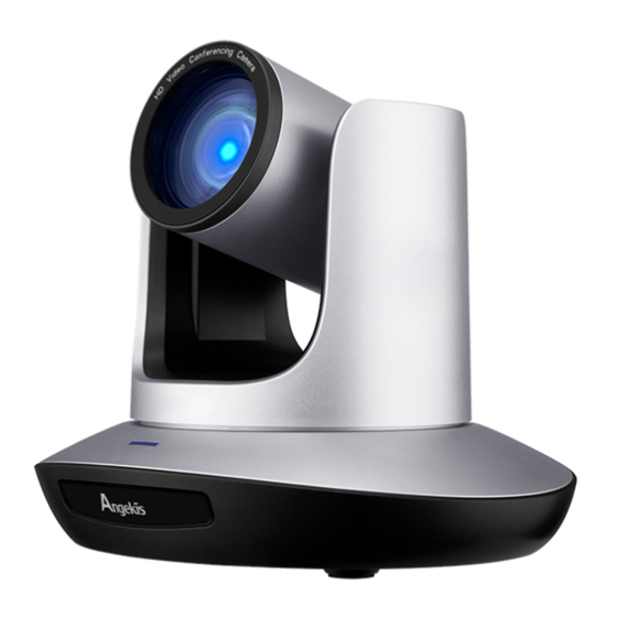
- Page 1 Saber IP20X Full NDI PTZ Camera User Manual(V1 .2) EN PLEASE REFER THIS DOCUMENT BEFORE USING. Note: NDI® is a registered trademark of Vizrt Group...
-
Page 2: Table Of Contents
CONTENTS CONTENT ............................1 SAFETY GUIDES ........................... 2 PACKING LIST ..........................3 QUICK START ..........................3 PRODUCT HIGHLIGHTS....................... 4 CAMERA SPEC ..........................5 CAMERA INTERFACE........................6 CAMERA DIMENSION........................6 IR REMOTE CONTROLLER......................7 VISCA IN (RS232 PORT)....................... 9 VISCA PROTOCOL ........................ -
Page 3: Safety Guides
SAFETY GUIDES 1. Before operation, please fully read and follow all instructions in the manual. For your safety, always keep this manual with the camera. 2. The camera power input range is 100-240V~AC(50-60Hz),ensure the power supply input within this rate before powering on. 3. -
Page 4: Packing List
PACKING LIST Check all bellow items when open the package: Camera······································································· 1 Power Adapter······························································ 1 Power Cable································································· 1 RS232 Control Cable····················································· 1 USB Type-C Cable························································ 1 Remote Controller························································· 1 User Manual································································· 1 Double-sided Adhesive··················································· 1 QUICK START Check all cable connections before power on. - 3 -... -
Page 5: Product Highlights
2.Dial Switch Setting (at the bottom of the camera): Dial Switch (ARM) SW-1 Instruction Updating mode Debugging mode Undefined Working mode Dial Switch Dial Switch SW-3 SW-4 Instruction SW-5 SW-6 Instruction Undefined Undefined Undefined Working mode Undefined Undefined Undefined Undefined PRODUCT HIGHLIGHTS ·... -
Page 6: Camera Spec
CAMERA SPEC 1920*1080P60/59.94/50/30/29.97/25/24/23.98 HDMI 1920*1080I60/59.94/50 1280*720P60/59.94/50/30/29.97/25 1920*1080P60/59.94/50/30/29.97/25/24/23.98 1920*1080I60/59.94/50 1280*720P60/59.94/50/30/29.97/25 YUY2 1920*1080P6; 1280*960P10; 1280*720P13; 1024*768P16; Video Format 800*600P25; 640*480P30; 640*480P30 MJPG 1920*1080P30; 1280*960P30; Type-C 1280*720P30; 1024*768P30; 800*600P30; 640*480P30; 640*480P30 1920*1080P60/59.94/50/30/29.97/25/24/23.98 ® 1920*1080I60/59.94/50 1280*720P60/59.94/50/30/29.97/25 ® Video Interface HDMI, SDI, USB Type-C, NDI Audio Interface Line-in ®... -
Page 7: Camera Interface
3D Noise Reduction Supported Anti Flicker OFF/50Hz/60Hz Pan Tilt Flip Supported Input Voltage DC12V/POE+(IEEE802.3at) Working -10 ~50 Working Humidity ≤80% Dimension 220mm×190mm×173mm Net Weight 1.45kg (3.2LBS) CAMERA INTERFACE 1. Camera Lens 6. Tripod Screw Hole 11. USB Type-C port 2. Camera Base 7. -
Page 8: Ir Remote Controller
- 7 -... - Page 9 - 8 -...
-
Page 10: Visca In (Rs232 Port)
VISCA IN (RS232 PORT VISCA V_IN V_OUT RS485 A(+) IR OUT B(-) VISCA IN &MiniDIN Connection VISCA IN & DB9 Connection Camera VISCA IN Camera VISCA IN Windows DB-9 Mini DIN A(+) A(+) IR OUT IR OUT B(-) B(-) VISCA Network Construction: - 9 -... -
Page 11: Visca Protocol
SERIAL PORT CONFIGURATION Parameter Value Parameter Value Baud rate 2400/4800/9600/115200 Stop Bit 1bit Start Bit 1 bit Check Bit None Date Bit 8 bit VISCA PROTOCOL Part1 Camera Return Command Ack/Completion Message Command Packet Note z0 41 FF Returned when the command is accepted. Completion z0 51 FF Returned when the command has been executed. - Page 12 Command type function command (0(wide) ~0x4000(tele)) 8x 01 04 06 02 FF 8x 01 04 06 03 FF Combine Combine with optical zoom 8x 01 04 36 00 FF Mode control Separate Separate with optical zoom 8x 01 04 36 01 FF Mode control CAM_DZoom...
- Page 13 Command type function command Reset 8x 01 04 04 00 FF 8x 01 04 04 02 FF Manual Control of B Gain CAM_B gain Down 8x 01 04 04 03 FF Direct 8x 01 04 44 00 00 0p 0q FF pq: B Gain (0-0xFF) Full Auto...
- Page 14 Command type function command Down 8x 01 04 02 03 FF pq: Aperture Gain Direct 8x 01 04 42 00 00 0p 0q FF (0~0x0F) Reset 8x 01 04 3F 00 pp FF pp: Preset Number(=0 to CAM_Memory(pres 127) 8x 01 04 3F 01 pp FF Corresponds to 0 to 9 on the Remote Commander Recall...
- Page 15 Command type function command 1080P30 0x04 1080P25 0x05 720P60 0x06 720P50 0x07 720P30 0x08 720P25 0x09 1080P5994 0x0E 1080I5994 0x0F 1080P2997 0x10 720P5994 0x13 720P2997 0x14 1080P24 0x11 1080P2398 0x12 Video format 1080P60 0x2e 1080P50 0x2f 1080I60 0x01 1080I50 0x04 1080P30 0x06 1080P25...
- Page 16 Command type function command P=4: BLUE P=5: RED&BLUE P=6: GREEN&BLUE P=7: RED&GREEN&BLUE 8x 01 06 01 VV WW 03 01 8x 01 06 01 VV WW 03 02 Down 8x 01 06 01 VV WW 01 03 Left 8x 01 06 01 VV WW 02 03 Right 8x 01 06 01 VV WW 01 01 Up left...
- Page 17 y0 50 02 FF Auto Focus CAM_Focus Mode Inq 8x 09 04 38 FF y0 50 03 FF Manual Focus CAM_Focus Pos Inq 8x 09 04 48 FF y0 50 0p 0q 0r 0s FF pqrs: Focus Position (0~0x01) CAM_2D_Inq 8x 09 04 A5 FF y0 50 03 FF p: 0: off...
- Page 18 Video System 8x 09 06 23 FF y0 50 pp FF pp: Video format Inq(Factory) Video System 8x 09 04 24 72 y0 50 0p 0p FF pp: Video format Inq(Sony) y0 50 02 FF IR_Transfer 8x 09 06 1A FF y0 50 03 FF Off...
-
Page 19: Pelco-D Protocol
PELCO-D Protocol Command List Function Byte1 Byte2 Byte3 Byte4 Byte5 Byte6 Byte7 0xFF Address 0x00 0x08 Pan Speed Tilt Speed Down 0xFF Address 0x00 0x10 Pan Speed Tilt Speed Left 0xFF Address 0x00 0x04 Pan Speed Tilt Speed Right 0xFF Address 0x00 0x02... -
Page 20: Pelco-P Protocol
PELCO-P Protocol Command List Function Byte1 Byte2 Byte3 Byte4 Byte5 Byte6 Byte7 Byte8 Tilt 0Xa0 Address 0x00 0x08 0Xaf Speed Speed Tilt Down 0Xa0 Address 0x00 0x10 0Xaf Speed Speed Tilt Left 0Xa0 Address 0x00 0x04 0Xaf Speed Speed Tilt Right 0Xa0 Address... -
Page 21: Osd Menu
OSD MENU 1. Under working mode, press the "MENU" key on the IR remote controller, to enter the OSD menu as bellow: 2. After enter the main menu, use the navigate "UP/DOWN" key to select the main menu. Once been selected, the main menu will change to blue background, and the right side will show all sub menu options. - Page 22 and IRIS mode. Gain setting: 0dB~30dB , only valid under MANUAL GAIN Default: AUTO mode. Bright setting: 0~27, only valid under BRIGHT priority EBRIGHT Default: AUTO mode. BRIGHT 0~15 Default: 8 WD MODE ON/OFF Default: OFF WD LEVEL WDR Level: 1~6 Default: 1 ON/OFF Default: OFF...
- Page 23 Speed By Zoom: proportional speed, the bigger the SPEEDBYZ Default: ON zoom is, the slower the speed is FLIP.HOR Flip horizontal Default: OFF FLIP VER Flip vertical Default: OFF SETTING PT SPD Pan Tilt speed Default: 18 ZOOM SPD Zoom speed Default: 5 PRE FRZ Open/Close Video Freeze when running presets...
-
Page 24: Set Ip Address In Menu
IR ADDR Camera IR control address CLIENT Default client end protocol: VISCA MODEL NO. Model number INFORMATION ARM VERSION ARM firmware version ISP VERSION USB firmware version FPGA VERSION FPGA firmware version RELEASE DATE Software release date Set IP Address in Menu In order to facilitate customer debugging, the camera has the support menu to set IP address. -
Page 25: Uvc Control
UVC CONTROL 1. Only run the client software after the USB3.0 camera has completed self-configuration (the IR indicator in blue color and will not flash); otherwise may cause black video issue. 2. Make sure the USB3.0 camera is recognized by the PC Device Manager. 3. -
Page 26: Web Setting
WEB SETTING After logging in, you can PTZF Control and Settings parameters for the camera on the web interface. The web interface supports Chrome, Firefox, IE, Safari, Opera and other browsers and is very adaptable. 1.Login Open the browser, enter the IP address (you need to check the corresponding IP address in the camera menu), enter the login screen, you can choose the language (Chinese, English, Korean, Russian, Spanish), enter the user name and password to login, as follows. - Page 27 After successful login the interface is shown above. (Not support image preview.) On the right side you can control the camera zoom, focus, preset position control and pan, tilt, other functions, and you can set the speed of the , focus and zoom pan/tilt speed speed...
- Page 28 The "Audio Settings" tab allows you to set the audio volume. As shown in the figure below: The "Image Adjust" tab contains pages for setting parameters such as focus, exposure, balance, image, image setting, and noise reduction. The following figure shows: The "Focus"...
- Page 29 The "Balance" tab contains parameters such as white balance mode, red gain, blue gain, and color temperature. The "Image" tab contains parameters such as Mirror, Flip, Backlight Compensation, Gamma, Wide Dynamic Range. After Wide Dynamic is turned on, the secondary option allows you to select the level of Wide Dynamic parameters.
- Page 30 The "Ethernet" tab contains DHCP mode, IP address, Netmask, Gateway, DNS, HTTP port, HTTPS port, VISCA Over IP port. The following figure shows: The "Firmware Upgrade" tab allows you to view the camera device number, serial number, ISP version, FPGA version, ARM version. In this interface, you can upgrade the camera program. The upgrade method is shown below, click the "Select a file"...
- Page 31 please log in to the "Reset Factory" tab on the WEB side to completely reset the camera. "Reset Option": reset the camera to default setting. Reset: reset camera image parameter. Reset Factory: reset camera Ethernet and image parameter, language and protocol will not be reset.
-
Page 32: Ndi Tools Guide
NDI Tools Guide 1. Image Preview https://ndi.tv/tools/ A. Download the NDI Tools via and install it. B. Find out the NDI Tools/Studio Monitor via Windows toolbars, and then open it, as bellow: C. Right click on the Studio Monitor screen, select the preview device: 2. - Page 33 3. Run WEB via Studio Monitor Refer to above picture, once open the video via Studio Monitor, there will show up a setting icon at the lower right corner, single click this iron to enter WEB UI. 4. How to use NDI tools to Virtual Input CAMERA A.
-
Page 34: Visca Over Ip
VISCA OVER IP VISCA over IP means VISCA protocol transmit via IP, to reduce RS232/RS485 cable layout (the controller must support IP communication function) Communication port spec: · · Control port: RJ45 Gigabit LAN IP protocol: IPv4 · · Transmit protocol: UDP IP address: set via web end or OSD menu ·... - Page 35 Note: LAN output way is big-endian, LSB is in the front. Payload type: Data definition as following: Name Value (Byte 0) Value (Byte 1) Value (Byte) VISCA Stores the VISCA command. 0x01 0x00 command VISCA inquiry 0x01 0x10 Stores the VISCA inquiry. Stores the reply for the VISCA command and VISCA reply 0x01...
- Page 36 0 for next time. The peripheral equipment will save sequence number of each command, and return the sequence number to the controller. Payload · · According to Payload type, the following data will be saved. VISCA command · · Save VISCA command packet VISCA inquiry ·...
- Page 37 If controller shows it is overtime, resend the commands to check peripheral’s status, resent command sequence number is same as last command, the following chart list the received message and status after resending the commands. Lost message Recelved Status after Correspondence after message for retransmission...
- Page 38 ® Copyright Angekis Technology Co., Ltd All Rights Reserved. FACEBOOK https://www.angekis.com...
Need help?
Do you have a question about the Saber IP20X and is the answer not in the manual?
Questions and answers