Advertisement
System Introduction
Before using the product, please read the simple operation manual and keep it in good condition.
System Overview
PM-320is a wireless monitoring system forstage performances and audiobroadcasting, and a wireless listening system forlarge simultaneous interpretation conferences. High-fidelity sound, advanced electronic processing technology instead ofthe traditional complicated and heavymonitoring equipment, eliminate the howling fromthe monitoring equipment, and make theperformance reliable and perfect.
System performance characteristics
- Metal 1/2 EIA standard1U case.
- The housing ofPM-320R receiver is madeof light-weight and toughalloy materials.
- Exquisite and simpleOLED display.
- The receiver uses theUHF frequency band, and the CPUcontrols diversity reception to reducedead spots and ensurestable reception.
- The bandwidth is 32MHzand there are 1280adjustable frequencies. 1-10 Channel groups, more than 180fixed frequencies for choose. Channelgroups U1-U5 can setand save frequencies freely.
- Stereo and monoselection.
- Treble boost function, limitcontrol function.
- The stable PLLphase-locked oscillation circuit, combined with the "noiselock" squelch can effectively block strayRF.
- With headphone monitoring output.
- With long transmissiondistance, it is suitable for variousoccasions.
Packing list

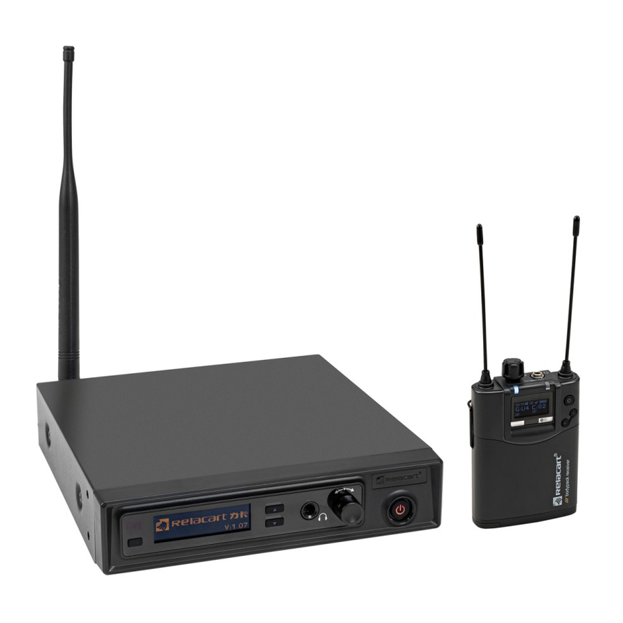
PM-320:
- Receiver *1
- Transmitter *1
- BNC antenna *1
- External power adapter*1
- 1.5VAA battery*2
- Stereo line*2
- 1U Rack mount kit (including screws) *1 set
- Simple operation manual *1
Transmitter function introduction
Front panel:

- Power switch (withindicator light).
- Function operation knob: turn this knobleft and right toselect the menu, press the knobto set the systemoperation menu.
- Headphone monitor jack, stereo output.
- "
![]() " Volume operation button: increase the inputvolume gain.
" Volume operation button: increase the inputvolume gain. - "
![]() " Volume operation button: attenuate the inputvolume gain.
" Volume operation button: attenuate the inputvolume gain. - OLED display: display frequency, frequency group and channel, batterylife, etc.
- Infrared data transmission (iR) window: Infrared pairing window, receivingthe data signal transmittedby the receiver.
- Infrared data transmissiondata (SYNC) button: Press this button totransmit the channel andsetting data of thetransmitter to the receiver.
 " Volume operation button: increase the inputvolume gain.
 " Volume operation button: attenuate the inputvolume gain.
Rear panel:

- Anti-pull device, used for powercord.
- The 12V connection jack (DCIN) of the external power adapter.
- A: 6.3 mm jack, the left sideis the audio output(LOOP OUT BAL 1/L).
B: 6.3 mm jack, the right sideis the audio output(LOOP OUT BAL 2/R). - A: XLR-3/6.3 mm combo jack, onthe left is theaudio input (BAL AFIN 1/L).
B: XLR-3/6.3 mm combojack, on the right isthe audio input (BALAF IN 2/R).
![warning]() Note: In mono mode, the signal from the left audio input terminal (XLR-3/6.3 mm combo jack, BAL AF IN 1/L) will be sent.
Note: In mono mode, the signal from the left audio input terminal (XLR-3/6.3 mm combo jack, BAL AF IN 1/L) will be sent. - BNC interface, antenna output interface.
 Note: In mono mode, the signal from the left audio input terminal (XLR-3/6.3 mm combo jack, BAL AF IN 1/L) will be sent.
Transmitter display overview

- Volume input: Display the setvolume input parameters.
- Radio frequency display: The device istransmitting radio signals.
- Transmit power: set transmit power. ( "
![]() " High transmit power, "
" High transmit power, " ![]() " low transmit power)
" low transmit power) - Audio mode: When mono isselected, it is displayed as "
![]() ", Pilot function is automaticallyturned off.
", Pilot function is automaticallyturned off.
When stereo isselected, it is displayed as "![]() ", Pilot function is automaticallyturned on.
", Pilot function is automaticallyturned on. - Control sound "P": Control sound analysishas been enabled. When stereo isselected, the pilot analysis sound isturned on automatically, and when mono isselected, the pilot analysis sound isturned off automatically.
- "Display Mode" status display:
A. Frequency: the set transmittingfrequency.
B. Group, channel: setgroup and channel.
C. Name: set name freely. - Key lock: The key lockis enabled on thetransmitter.
- Audio frequency: left (AF L) and right(AF R) audio channels, indicating the levelof audio input.
 " High transmit power, "
  " low transmit power)
Receiver Function Introduction

- Antennas A andB.
- Power switch/volume potentiometer.
- 3.5mm stereo headphone monitor jack.
- Antenna A indicator: When the batterylevel shows 1 bar, theantenna indicator changes fromblue to red.
- Antenna B indicator: Whenthe battery level shows1 ba, the antenna indicatorchanges from blue tored.
- OLED display: display frequency, frequency group channel, batterylife, etc.
- Infrared data transmission window (iR): Infrared frequency window, which transmits the channel data of the receiver to the transmitter, so that the frequency of the transmitter and the receiver are consistent.
- SET key: enter the menu/or confirm the menu settings.
- "
![]() /
/![]() ": select function operation keys.
": select function operation keys. - Belt clip: fix the receiver around the waist of the user.
- Battery compartment: fill 2 AA batteries. (It is best to use alkaline 1.5V AA batteries. Please replace two batteries at the same time when replacing new batteries. )
![]()
Do not install the battery with wrong polarity, which may damage the internal electronic parts. - Battery cover lock switch: Push this switch to open the battery cover.
 /
/ ": select function operation keys.
Receiver display overview

- Squelch Threshold: Displays the set squelch threshold parameters.
- Pilot control tone.
- Audio mode: When mono is selected, it is displayed as "
![]() ", Pilot function is automatically turned off.
", Pilot function is automatically turned off.
When stereo is selected, it is displayed as "![]() ", Pilot function is automatically turned on.
", Pilot function is automatically turned on. - Key lock: Key lock is enabled on the receiver.
- Battery status: 4 bars are fully charged, please replace with new ones in time when there is one bar left.
- "Display Mode" status display:
A. Frequency: the set transmitting frequency.
B. Group, channel: set group and channel.
C. Name: freelyset name. - "AF" audio frequency: indicates the audio input level of the transmitter.
- "RF" radio signal level: the strength of the received radio signal.
Menu
Transmitter

Receiver

System installation and connection
System installation
- In order toachieve the best operationof the equipment, the height ofthe receiver should behigher than 1 meterfrom the bottom andat least 1 meterfrom the wall surface.
- Keep the antennaaway from interference sources, such as computerequipment, digital equipment, televisions and cars, and also awayfrom large-area metal objects.
- Install the antenna on the antenna connector on the rear panel, and pull the antenna to a position at a 45° angle to the vertical.
- Minimize obstacles as muchas possible between thelocation of the receiverand the place wherethe transmitter is used.
- When two transmittersare used at thesame time, the distance between thetransmitter and the receivermust be at least2 meters.
System connection
- Connect the outputend of the DC12V/1000mADC output power supplyto the transmitter DC powerinput socket. To prevent theDC plug from accidentallydetaching, first pass the wirethrough the fixing holeand then tighten it.
(![warning]() Note: The input voltage ofthe AC power adaptermust be selected to meetthe power supply specificationrange of the areaof use.)
Note: The input voltage ofthe AC power adaptermust be selected to meetthe power supply specificationrange of the areaof use.) - There are two types of audio jacks on the rear panel of the transmitter, namely Φ6.3mm balanced output socket and XLR-3/6.3 mm combined balanced input jack.
- Use a suitable cable to connectthe output of anexternal device (such as a mixeror a second PM-320TX) to theXLR-3/6.3 mm combinedbalanced input jack.
- Use a suitable cable to connect the input end of an external device (such as a mixer or a second PM-320TX) to the Φ6.3 mm balanced output jack.
(![warning]() Note: After the signalsof the input jacks BAL AFIN 1/L and BALAF IN 2/R areseparated, they continue to betransmitted to the outputjacks LOOP OUT BAL1/L and LOOP OUTBAL 2/R. Therefore, you can only transmit. Use the output jack whenthe machine is switchedon.)
Note: After the signalsof the input jacks BAL AFIN 1/L and BALAF IN 2/R areseparated, they continue to betransmitted to the outputjacks LOOP OUT BAL1/L and LOOP OUTBAL 2/R. Therefore, you can only transmit. Use the output jack whenthe machine is switchedon.)
- Set the appropriateaudio input level
The intensity of theaudio input signal willbe displayed on theAF level meter onthe OLED display panel, andthe intensity of theinput audio signal willbe adjusted appropriately. Therefore, the input intensitymust be adjusted appropriately to obtainthe best signal-to-noise ratio anddynamic range, and to avoidsignal distortion. - Headphone connection
Insert the monitor headphoneconnection plug into the3.5mm headphone stereo socket, youcan also connect generalheadphones or connect theoutput end to theaudio input of otheraudio equipment.
![warning]() Note: The headphone output socketis a stereo output. Notethat the connected plug mustbe a stereo plug. Ifit is a monoheadphone plug, one side of theoutput may be short-circuitedand the headphone output circuiton the other sidemay be burned.
Note: The headphone output socketis a stereo output. Notethat the connected plug mustbe a stereo plug. Ifit is a monoheadphone plug, one side of theoutput may be short-circuitedand the headphone output circuiton the other sidemay be burned. - Multi-system mixed groupconnection mode
Some performers need tohear the signal oftheir own playing instrumentand the mixed instrument. Withthe help of thisdevice, each performer can hearthis "combination" effect ortheir independent performance effect, and send a whole band fromthe mixer Mix theeffect to the firsttransmitter (PM-320T) BALAF IN 1/L andBAL AF IN 2/Rinput terminals, and then from theLOOP OUT BAL 1/Land LOOP OUT BAL2/R output terminals, connect To theBAL AF IN 1/Land BAL AF IN2/R inputs of a transmitter. Using this link, you can operateall transmitters, and create a mixerto listen to eachperformer through the auxiliary output of the mixer. Send these different combinations to each performer's receiver (PM-320R).
System equipment connection diagram

Specification
PM-320R Stereo Mini Receiver
| Receiving method | antenna diversity reception |
| Carrier frequency band | 554MHz~936 MHZ |
| Maximum deviation | ±48KHz |
| Number of channel groups | single channel |
| Modulation method | FM MPX (stereo) |
| S/N ratio | >100dB |
| T.H.D. | <0.9%@1KHz |
| Stereo separation | ≥55dB, at 1KHz |
| Frequency response | 25Hz-15KHz ±3dB |
| Battery | AAx2 |
| Current consumption | 165mA (typical) |
| Battery life | > 8 hours |
| High frequency boost | +8 dB at 10KHz |
| Limiter | each step can be adjusted 6dB, can be turned off |
| Frequency stability | ±0.005% (0~50°C) |
| Oscillation mode | PLL phase lock frequency synthesis |
| Working distance | 100 meters in general (open area) |
| Output socket | φ3.5mm stereo headphone socket |
| Output power | 2x150mW at 1KHz (T.H.D.: 3%) |
| Sensitivity | When the offset is equal to 25KHz, 6dBuV, S/N>60dB |
| Frequency bandwidth | 32MHz (1280 transmitting frequencies, tunable in units of 25 KHz) |
| Dimensions | 90mm (height) x 65mm (width) x 23mm (depth) |
| Weight | about 100g |
PM-320T Stereo Transmitter
| Main Frame Size | 1 / 2 EIA standard 1U |
| Frequency band | 554MHz~936 MHz |
| Maximum deviation | ±50KHz |
| Number of channel groups | single channel |
| Modulation method | FM MPX (stereo) |
| S/N ratio | >100dB |
| T.H.D. | <0.9%@1KHz |
| Frequency bandwidth | 32MHz |
| Comprehensive frequency response | 25Hz-15KHz ±3dB |
| Output power | 30mW-50mW |
| Current consumption | 140mA (typical) |
| Power supply mode | DC 12V |
| Frequency stability | ±0.005% (-10~50°C) |
| Oscillation mode | PLL phase lock frequency synthesis |
| Harmonic radiation | more than 60dB lower than the main wave |
| Audio output | φ6.3mm balanced socket x2 |
| MPX control tone | frequency: 19KHz, deviation: ±5KHz |
| Audio input | Line level x 2, XLR and φ6.3mm co composite socket |
| Dimensions | 206mm (width) x 44mm (height) x 199mm (depth) |
| Weight | about 955g |

Documents / ResourcesDownload manual
Here you can download full pdf version of manual, it may contain additional safety instructions, warranty information, FCC rules, etc.
Advertisement


Need help?
Do you have a question about the PM-320 and is the answer not in the manual?
Questions and answers