Advertisement
Quick Links
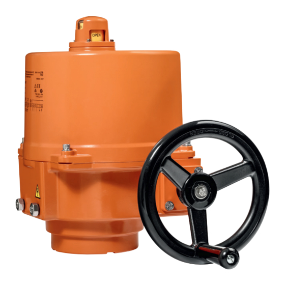
SY(2...5)U24-SR/MF/MP-T modulating actuator
SY(2...9)U230-SR/MF-T actuator
Wiring diagram
Connect via safety
!
isolating transformer
AC 24 V
Y
U5
C
C
1
2
1
2
+
+
-
-
Note: 1) Power supply Com/Neutral and control signal " - " wiring
to a common is prohibited.
!
Incorrect wiring will damage the actuator!
2) 75% duty cycle
Circuit Board Set Up
SY(2...5)U24-SR/MF/MP-T
SY(2...9)U230-SR/MF-T
Before power on, make sure the input signal and voltage wiring are
in accordance with the actuator nameplate.
If it's necessary to change the following settings, only
!
authorized and trained persons are allowed to do that.
Install to butterfly valve
1).
Manual operate the actuator
to the similar open position
of the valve, which can be
judged by the valve disc or
the red line on the valve top
stem.
2).
Fit coupling on the top stem
of the valve.
3).
Mount the actuator onto the
coupling, manual operate
the actuator to align the holes
of valve top flange and actu-
ator bottom; then tighten the
bolts by wrench in diagonal
sequence.
4).
Uncover the actuator, wire
according to the wiring diag-
ram, check the DIP switch
setting.
5).
Power on to test run the
actuator, check its stroke
and feedback position, do
some adjustment if necessary.
6).
Put the cover on and tighen
the bolts for it.
Auxilary Switches
(SPDT Relays)
AC 230 V
A
B
C
D
E
F
N L
S1 100%
S2 0%
SY(2...5)U24-SR/MF/MP-T
SY(2...9)U230-SR/MF-T
Direction switch
Y2 standard
Direction switch
Y2 standard
The line indicates
the position of the
valve's disc
± 1°
Limit switches LS.. with travel cams TC..
The TC.. cams operating the LS.. limit switches rotate with the shaft.
Clockwise movement of the shaft closes the actuator, counterclockwise
opens the actuator.
There are 4 cams included , marked with two colors : blue for open,
silver for close; each cam can be set independently.
shaft
LS4
LS3
LS2
LS1
SY(2...5)U24-SR/MF/MP-T
SY(2...9)U230-SR/MF-T
1. How to adjust the travel cam
Perform an adaption after changing
the position of the travel cam.
Loosen the cam to be adjusted
1.1
with a 2.5 mm allen key;
By turning the key rotate and
1.2
adjust the cam as shown in
the right diagram;
Commission;
1.3
Tighten the cam after succes-
1.4
sful adjustment.
2. Closed position (0%) setting
Power on. The actuator will stop.
2.1
Adjust travel cam TC2 in the closed position.
2.2
(The fanshaped cam which connected with the potentiometer need
to be loosed firstly, then retightened after the travel limit switches
setting is terminated.)
Check whether LS2 switch trips prior to manual operation stop.
2.3
(So when motor stops at fully closed position, it should be
possible to further operate the handwheel CW 1/2...3/4 turn.
Otherwise the stop screw for close need to be adjusted.)
Proceed in the similar way for TC1 in open position.
Limiting of manual rotation with stop screws
SY quarter-turn actuator is provided with a limiting of manual rotation
device to avoid over-travel with the handwheel going beyond the 1/4-turn
rotation.
The actuator is supplied and tested for
...92° limiting of manual rotation.
The limiting of manual rotation is realized by the stop screws 1 and 2
( max. ± 2° which corresponding to 1 turn of the stop screw).
The stop screws must be sec-
ured with the lock nut after any
adjustment. (by both a allen key
and a wrench)
The 90° travel must always be
limited by the travel limit sw-
itches so they must be set to
trip just BEFORE stop screw's
contact.
To achieve this, loose
stop screws by 2 1/2 turns. Then,
after travel limit switch setting is
terminated, (see paragraph
Limit switches LS.. with travel cams
rically to closed position. Now rotate the stop screw 2 to closed position,
re-loose 1 turn, and secure by lock nut. Proceed in the same way for stop
screw 1 in open position.
It is emphasized that the limiting of manual rotation device is only a design
feature to prevent over-travel when the actuator is being operated manually,
not a safety function to prevent over-travel in the event of travel limit
switch failure.
Auxiliary switch for closed
TC4
(factory setting 3°)
Auxiliary switch for open
TC3
(factory setting 87°)
Closed switch
(factory setting 0°)
TC2
Open switch
(factory setting 90°)
TC1
Adaption button
Open
Current position
Required position
90°
electrical operation, and -2°
1
2
1- Stop screw for manual OPEN limit
2- Stop screw for manual CLOSED limit
3- Handwheel connection
(Note: SY1 without the device)
TC..), operate the actuator elect-
Close
3
Advertisement

Subscribe to Our Youtube Channel
Related Manuals for Belimo SY U24-SR Series


Summary of Contents for Belimo SY U24-SR Series
- Page 1 SY(2...5)U24-SR/MF/MP-T modulating actuator SY(2...9)U230-SR/MF-T actuator Wiring diagram Limit switches LS.. with travel cams TC.. Auxilary Switches Connect via safety The TC.. cams operating the LS.. limit switches rotate with the shaft. (SPDT Relays) isolating transformer Clockwise movement of the shaft closes the actuator, counterclockwise opens the actuator.
- Page 2 SY(2...5)U24-SR/MF/MP-T 调节型执行器 SY(2...9)U230-SR/MF-T 执行器 限位开关 LS.. 与行程凸轮 TC.. 接线说明 通过安全隔离 行程凸轮TC.. 随轴的转动使电子行程开关LS.. 动作。 辅助开关 的变压器连接 轴顺时针方向转动时执行器关闭,逆时针转动时执行器打开。 共有4个行程凸轮,以两种颜色标记:蓝色表示控制打开状态, AC 230 V AC 24 V 银行表示控制关闭状态;任何一个行程凸轮都可以单独调整。 S1 100% S2 0% 轴 SY(2...5)U24-SR/MF/MP-T 辅助开关用于全关位置反馈 SY(2...9)U230-SR/MF-T (出厂设置 3°) 注: 1) 禁止将电源零线与控制信号零线共线。 辅助开关用于全开位置反馈 错误的接线可能会损坏执行器。 (出厂设置 87°) 用于全关限位开关定位(出厂设置...
Need help?
Do you have a question about the SY U24-SR Series and is the answer not in the manual?
Questions and answers