Table of Contents
Advertisement
Quick Links
Advertisement
Chapters
Table of Contents

Related Manuals for Omega OTEC IEMP-D Series


Summary of Contents for Omega OTEC IEMP-D Series
- Page 1 IEMP-D Series Ducted Fan Coil Technical Manual...
- Page 2 Applicable Models: Indoor units: Outdoor unit ICHD009J0A-DMG026 Medium Static Pressure Duct ICHD012J0A-DMG035 IEMP009J3A-DCG026 ICHD018J0A-DMG053 IEMP012J3A-DCG035 ICHD024J0A-DMG071 IEMP018J3A-DCG053 ICHD031J0A-DMG090 IEMP024J3A-DCG071 ICHD036J0A-DMG105 IEMP031J3A-DCG090 ICHD042J0A-DMG120 IEMP036J3A-DCG105 ICHD048J0A-DMG140 IEMP042J3A-DCG120 ICHD060J0A-DMG160 IEMP048J3A-DCG140 IEMP060J3A-DCG160...
- Page 3 Content Part. 1 General information ............2 Part. 2 Outdoor Unit ..............6 Part. 3 Indoor Unit ..............18 Part. 4 Installation & Troubleshooting ........107...
- Page 4 Part. 1 General information 1. Model Names of Indoor/Outdoor Units ......3 2. External Appearance ............4...
- Page 5 1. Model Names of Indoor/Outdoor Units Indoor unit Outdoor unit Type Model Power supply Model Power supply Medium static pressure duct IEMP009J3A 220-240V~, 1Ph, 50Hz ICHD009J0A 220-240V~, 1Ph, 50Hz Medium static pressure duct IEMP012J3A 220-240V~, 1Ph, 50Hz ICHD012J0A 220-240V~, 1Ph, 50Hz Medium static pressure duct IEMP018J3A 220-240V~, 1Ph, 50Hz...
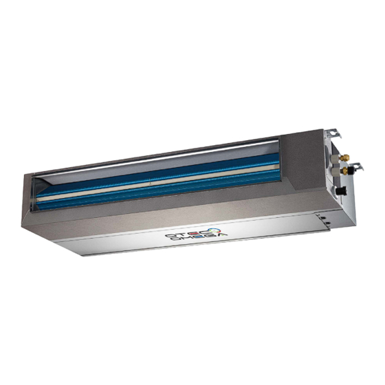
- Page 6 2. External Appearance 2.1 Indoor units IEMP009J3A / IEMP012J3A / IEMP018J3A / IEMP024J3A IEMP031J3A / IEMP036J3A / IEMP042J3A / IEMP048J3A / IEMP060J3A 2.2 Outdoor unit ICHD009J0A / ICHD012J0A / ICHD018J0A/ ICHD024J0A ICHD031J0A/ ICHD036J0A / ICHD042J0A / ICHD048J0A/ ICHD060J0A...
-
Page 7: Table Of Contents
Part. 2 Outdoor Unit 1. Specifications ..............7 2. Dimension (Unit:mm) ............9 3. Refrigerant circuit ............. 10 4. Wiring Diagrams ..............14 5. Electric Characteristics ............ 16 6. Sound Levels ..............17 7. Accessories ............... 17... -
Page 8: Specifications
1. Specifications Table 1.1: ICHD009, 012, 018, 024 specifications Model name ICHD009J0A ICHD012J0A ICHD018J0A ICHD024J0A Power supply V/Ph/Hz 220-240/1/50 Power input 649(210~1350) 1159(240~1460) 1602(370~2380) 2115(520~2890) Cooling Power input (Maximum) 1620 1900 2800 3500 Power input 859(190~1250) 1209(230~1570) 1902(390~2490) 2615(460~3310) Heating Power input (Maximum) 1900 1720... - Page 9 Table 1.2: ICHD031, 036, 042, 048 specifications 10.5 Model name ICHD031J0A ICHD036J0A ICHD042J0A ICHD048J0A Power supply V/Ph/Hz 220-240/1/50 3109(529-3909) Power input 3060(670~3480) 4559(529~5009) 5809(1200~6100) Cooling Power input (Maximum) 4700 4609 5469 7000 3009(509-4009) Power input 2900(650~3570) 3909(509~4009) 4909(1000~5200) Heating Power input (Maximum) 4700 4520 4520...
- Page 10 Table 1.3: ICHD060 specifications Model name ICHD060J0A Power supply V/Ph/Hz 220-240/1/50 Power input 6600(1340~6600) Cooling Power input (Maximum) 7465 Power input 5800(1120~5800) Heating Power input (Maximum) 7465 Type Rotary DC Inverter Quantity Compressor Oil type ESTER OIL VG74 Start-up method DC Inverter Starting Type WZDK170-38G-1...
-
Page 11: Dimension (Unit:mm)
2. Dimension (Unit: mm) ICHD009J0A-DMG026 / ICHD012J0A-DMG035 / ICHD018J0A-DMG053 / ICHD024J0A-DMG071 Model 35/53 ICHD031J0A-DMG090 / ICHD036J0A-DMG105 / ICHD042J0A-DMG120 / ICHD048J0A-DMG140 / ICHD060J0A-DMG160 Model 105/120/140 1040... -
Page 12: Refrigerant Circuit
3. Refrigerant circuit ICHD009J0A-DMG026 / ICHD012J0A-DMG035 E S C Compressor Silencer Four-way reversing valve Silencer Condenser Fan blade Motor Heating spool Refrigerant cooling module Throttling capillary Stop valve (liquid side) Evaporator Outdoor unit wind wheel Indoor unit motor Stop valve (gas side) Temperature control switch Indoor temperature sensor Temperature sensor in the middle of evaporator... - Page 13 ICHD018J0A-DMG053 E S C Compressor Silencer Four-way reversing valve Silencer Condenser Fan blade Motor Heating spool Refrigerant cooling module Refrigeration spool Stop valve (liquid side) Evaporator Outdoor unit wind wheel Indoor unit motor Stop valve (gas side) Temperature control switch Indoor temperature sensor Temperature sensor in the middle of evaporator Condenser outlet temperature sensor...
- Page 14 ICHD024J0A-DMG071 E S C Compressor Silencer Four-way reversing valve Silencer Condenser Fan blade Motor Heating spool Refrigerant cooling module Refrigeration spool Stop valve (liquid side) Evaporator Outdoor unit wind wheel Indoor unit motor Stop valve (gas side) Temperature control switch Indoor temperature sensor Temperature sensor in the middle of evaporator Condenser outlet temperature sensor...
- Page 15 ICHD031J0A-DMG090 ICHD036J0A-DMG105 ICHD042J0A-DMG120 ICHD048J0A-DMG140 ICHD060J0A-DMG160 E S C Compressor Silencer Four-way reversing valve Silencer Condenser Fan blade Motor Heating spool Refrigerant cooling module Refrigeration spool Filter Stop valve (liquid side) Evaporator Outdoor unit wind wheel Indoor unit motor Stop valve (gas side) Gas liquid separator Low voltage switch Indoor temperature sensor...
-
Page 16: Wiring Diagrams
4. Wiring Diagrams ICHD009J0A-DMG026 / ICHD012J0A-DMG035 ICHD018J0A-DMG053 / ICHD024J0A-DMG071 Outdoor wire diagram DC Fan CN414 Four Way Valve CN60 CN23 Debug Board Brown L-IN Outdoor main Controller Blue Blue Blue CN 27 N -IN C N2 8 Black Black Black CN 29 E arth CN17... - Page 17 ICHD031J0A-DMG090...
- Page 18 ICHD036J0A-DMG105 / ICHD042J0A-DMG120 / ICHD048J0A-DMG140...
- Page 19 ICHD060J0A-DMG160...
-
Page 20: Electric Characteristics
5. Electric Characteristics Model Power Supply Compressor Volts Capacity Min.volts Max.volts TOCA ICHD009-DMG026 220-240 0.02 ICHD012-DMG035 50 220-240 0.02 ICHD018-DMG053 50 220-240 12.9 14.5 7.85 0.05 0.71 50 220-240 ICHD024-DMG071 17.5 8.85 0.08 ICHD031-DMG090 50 220-240 11.8 0.08 ICHD036-DMG105 50 220-240 28.5 14.5 0.17... -
Page 21: Sound Levels
6. Sound Levels ICHD009, 012, 018, 024, 031, 036, 042, 048 Front (H+1)/2 m Notes: H is the height of ODU ICHD060 Front (H+1)/2 m 1.3m Notes: H:The height of ODU Unit Number Model Noise Level (dB(A)) ICHD009J0A-DMG026 ICHD012J0A-DMG035 ICHD018J0A-DMG053 ICHD024J0A-DMG071 ICHD031J0A-DMG090 ICHD036J0A-DMG105... -
Page 22: Accessories
7. Accessories Accessory name of outdoor unit Qty. Purpose Seal ring For drainage of ODU Water outlet joint... - Page 23 Part. 3 Indoor Unit 1.Specifications ............... 19 2.Dimensions (Unit: mm) ............21 3.Wiring Diagrams ..............32 4.Capacity Table ..............23 5.Static Pressure Curve ............46 6.Electric Characteristics ............48 7.Sound Levels ................ 49 8. Accessories ................. 49...
- Page 24 1. Specifications Table 1.1: IEMP009, 012, 018, 024 specifications IEMP024J3A Model name IEMP009J3A IEMP012J3A IEMP018J3A Power supply 1-phase, 220-240V, 50Hz Capacity 2600(700~3500) 3500 (750~3700) 5300(1100~5900) 7200(2400~8200) Input(IDU+ODU) 740(210~1350) 1250(240~1460) 1700W(370~2380) 2250(520~2890) Cooling Input(IDU) 97.5 134.8 3.51 2.80 3.12 3.20 Capacity 3600(700~3700W) 4150(800~4600) 6200 (1600~6800)
- Page 25 Table 1.2: IEMP036, 042, 048 specifications Model name IEMP031J3A IEMP036J3A IEMP042J3A IEMP048J3A Power supply 1-phase, 220-240V, 50Hz Capacity 9000(2700~9600) 10500(3000~11200) 12000(3000~12000) 13800(4200~13800) Input 3060(670-3480) 3400(820-4200) 4850(820~5300) 6100(1200~6100) Cooling (IDU+ODU) Input(IDU) 3.08 3.09 2.47 2.26 Capacity 10000(2800~10500) 11600(3100~12800) 13200(3100~13200) 16000(4500~16000) 3300(800-4300) Input(IDU+ODU) 2900(650-3570) 4200(800~4300)
- Page 26 Table 1.3: IEMP060J3A-DCG160 specifications Model name IEMP060J3A Power supply 1-phase, 220-240V, 50Hz Capacity 15500(4430~15500) Input 6600(1340~6600) Cooling (IDU+ODU) Input(IDU) 2.35 Capacity 17200(4720~17200) Input(IDU+ODU) 5800(1120~5800) Heating Input(IDU) 2.97 Model YSK180-4P Type Ac motor Fan motor Brand Welling Speed (H/M/L) r/min 1080/960/710 Number of rows Tube pitch ×...
- Page 27 2. Dimensions (Unit: mm) 2.1 Medium Static Pressure Duct External dimensions and size of air outlet duct Size of return air inlet (back return air mode) Size of return air inlet (bottom return air mode), and the distance between the lugs IEMP009(012)J38 IEMP018J38- IEMP024J38-...
- Page 28 3. Wiring Diagrams 3.1 Medium Static Pressure Duct IEMP009J3A-DCG026 / IEMP012J3A-DCG035 / IEMP018J3A-DCG053 / IEMP024J3A-DCG071...
- Page 29 IEMP031J3A-DCG090 / IEMP060J3A-DCG160...
- Page 30 IEMP036J3A-DCG105 / IEMP042J3A-DCG120 / IEMP048J3A-DCG140...
- Page 31 4. Capacity Table 4.1 Medium Static Pressure Duct Model IEMP009J3A-DCG026 Cooling mode: Indoor air temperature (°C WB/DB) Outdoor air Capacity(kW) temperature 14/20 16/23 18/26 19/27 20/28 22/30 24/32 (°C DB) Airflow rate(m3/h) 10.00 3.32 2.66 3.44 2.75 3.56 2.85 3.60 2.52 3.64 2.55...
- Page 32 46.00 2.30 1.84 2.42 1.94 2.54 2.03 2.58 1.81 2.62 1.83 2.70 1.89 2.78 1.95 48.00 2.22 1.78 2.34 1.87 2.46 1.97 2.50 1.75 2.54 1.78 2.62 1.83 2.70 1.89 50.00 2.14 1.71 2.26 1.81 2.38 1.90 2.42 1.69 2.46 1.72 2.54 1.78...
- Page 33 Heating mode: Indoor air temperature (°C DB) Capacity(kW) Outdoor air temperature (°C) Airflow rate(m3/h) -15.30 -15.00 2.50 2.40 2.30 2.25 2.20 2.10 -13.00 -12.60 2.62 2.52 2.42 2.37 2.32 2.22 -11.00 -10.50 2.73 2.63 2.53 2.48 2.43 2.33 -9.50 -10.00 2.78 2.68 2.58...
- Page 34 -7.60 -7.00 2.40 2.30 2.20 2.15 2.10 2.00 -5.60 -5.00 2.50 2.40 2.30 2.25 2.20 2.10 -3.70 -3.00 2.60 2.50 2.40 2.35 2.30 2.20 -0.70 0.00 2.75 2.65 2.55 2.50 2.45 2.35 2.20 3.00 2.90 2.80 2.70 2.65 2.60 2.50 4.10 5.00 3.00...
- Page 35 Model IEMP012J3A-DCG035 Cooling mode: Indoor air temperature (°C WB/DB) Capacity(kW) Outdoor air 14/20 16/23 18/26 19/27 20/28 22/30 24/32 temperature (°C DB) Airflow rate(m3/h) 10.00 4.28 3.42 4.43 3.54 4.58 3.66 4.63 3.24 4.68 3.27 4.78 3.34 4.88 3.41 12.00 4.19 3.35 4.34...
- Page 36 39.00 3.40 2.72 3.55 2.84 3.70 2.96 3.75 2.62 3.80 2.66 3.90 2.73 4.00 2.80 42.00 3.16 2.53 3.31 2.65 3.46 2.77 3.51 2.46 3.56 2.49 3.66 2.56 3.76 2.63 44.00 3.00 2.40 3.15 2.52 3.30 2.64 3.35 2.34 3.40 2.38 3.50 2.45...
- Page 37 Heating mode: Indoor air temperature (°C DB) Capacity(kW) Outdoor air temperature (°C) Airflow rate(m3/h) -15.30 -15.00 1.83 1.67 1.51 1.43 1.35 1.19 -13.00 -12.60 2.12 1.96 1.80 1.72 1.64 1.48 -10.50 -11.00 2.37 2.21 2.05 1.97 1.89 1.73 -10.00 -9.50 2.49 2.33 2.17...
- Page 38 21.41 23.00 6.20 6.04 5.88 5.80 5.72 5.56 24.00 22.37 6.27 6.11 5.95 5.87 5.79 5.63 -15.30 -15.00 1.22 1.06 0.90 0.82 0.74 0.58 -13.00 -12.60 1.51 1.35 1.19 1.11 1.03 0.87 -11.00 -10.50 1.76 1.60 1.44 1.36 1.28 1.12 -10.00 -9.50 1.88...
- Page 39 Model IEMP018J3A-DCG053 Cooling mode: Indoor air temperature (°C WB/DB) Capacity(kW) Outdoor air 14/20 16/23 18/26 19/27 20/28 22/30 24/32 temperature (°C DB) Indoor Airflow(m3/h) 10.00 7.64 5.35 7.73 5.41 7.82 5.48 7.85 5.42 7.89 5.45 7.97 5.50 8.05 5.56 12.00 7.51 5.25 7.60...
- Page 40 44.00 4.24 2.96 4.33 3.03 4.42 3.09 4.45 3.07 4.49 3.09 4.57 3.15 4.65 3.21 46.00 4.05 2.83 4.14 2.89 4.23 2.96 4.26 2.94 4.30 2.96 4.38 3.02 4.46 3.07 48.00 3.86 2.70 3.95 2.76 4.04 2.82 4.07 2.80 4.11 2.83 4.19 2.89...
- Page 41 Heating mode: Indoor air temperature (°C DB) Capacity (kW) Outdoor air temperature (°C) Indoor Airflow(m3/h) -15.30 -15.00 3.70 3.34 2.98 2.81 2.64 2.30 -13.00 -12.60 4.15 3.79 3.43 3.26 3.09 2.75 -11.00 -10.50 4.53 4.17 3.81 3.64 3.47 3.13 -10.00 -9.50 4.72 4.36...
- Page 42 21.41 23.00 8.52 8.16 7.80 7.63 7.46 7.12 22.37 24.00 8.62 8.26 7.90 7.73 7.56 7.22 -15.30 -15.00 1.66 1.30 0.94 0.77 0.60 0.26 -13.00 -12.60 2.10 1.74 1.38 1.21 1.04 0.70 -11.00 -10.50 2.49 2.13 1.77 1.60 1.43 1.09 -10.00 -9.50 2.68...
- Page 43 Model IEMP024J3A-DCG071 Cooling mode: Indoor air temperature (°C WB/DB) Capacity(kW) Outdoor air 14/20 16/23 18/26 19/27 20/28 22/30 24/32 temperature (°C DB) Indoor Airflow(m3/h) 10.00 10.12 7.09 10.21 7.15 10.30 7.21 10.33 7.13 10.37 7.16 10.45 7.21 10.53 7.27 12.00 9.93 6.95 10.02...
- Page 44 44.00 6.09 4.26 6.18 4.33 6.27 4.39 6.30 4.35 6.34 4.37 6.42 4.43 6.50 4.49 46.00 5.89 4.12 5.98 4.19 6.07 4.25 6.10 4.21 6.14 4.24 6.22 4.29 6.30 4.35 48.00 5.69 3.98 5.78 4.05 5.87 4.11 5.90 4.07 5.94 4.10 6.02 4.15...
- Page 45 Heating mode: Indoor air temperature (°C DB) Capacity (kW) Outdoor air temperature (°C) Indoor Airflow(m3/h) -15.30 -15.00 4.60 4.18 3.76 3.56 3.36 2.96 -13.00 -12.60 5.20 4.78 4.36 4.16 3.96 3.56 -11.00 -10.50 5.73 5.31 4.89 4.69 4.49 4.09 -10.00 -9.50 5.98 5.56...
- Page 46 21.41 23.00 10.84 10.42 10.00 9.80 9.60 9.20 22.37 24.00 10.94 10.52 10.10 9.90 9.70 9.30 -15.30 -15.00 2.53 2.11 1.69 1.49 1.29 0.89 -13.00 -12.60 3.13 2.71 2.29 2.09 1.89 1.49 -11.00 -10.50 3.66 3.24 2.82 2.62 2.42 2.02 -10.00 -9.50 3.91...
- Page 47 Model IEMP031J3A-DCG090 Cooling mode: Indoor air temperature (°C WB/DB) Capacity(kW) Outdoor air 14/20 16/23 18/26 19/27 20/28 22/30 24/32 temperature (°C DB) Indoor Airflow(m3/h) 10.00 10.87 7.03 11.14 7.09 11.32 7.09 11.50 7.19 11.76 7.47 12.02 7.75 12.15 7.94 12.00 10.67 7.00 10.94...
- Page 48 42.00 7.69 6.10 7.96 6.22 8.14 6.26 8.32 6.27 8.58 6.57 8.84 6.87 8.97 7.07 44.00 7.19 5.77 7.46 5.89 7.64 5.94 7.82 5.96 8.08 6.25 8.34 6.55 8.47 6.75 46.00 6.69 5.43 6.96 5.56 7.14 5.62 7.32 5.64 7.58 5.93 7.84 6.22...
- Page 49 Heating mode: Indoor air temperature (°C DB) Capacity (kW) Outdoor air temperature (°C) Indoor Airflow(m3/h) -15.30 -15.00 4.46 4.26 4.06 3.96 3.86 3.66 -13.00 -12.60 5.11 4.91 4.71 4.61 4.51 4.31 -11.00 -10.50 5.68 5.48 5.28 5.18 5.08 4.88 -10.00 -9.50 5.95 5.75...
- Page 50 22.37 24.00 12.52 12.32 12.12 12.02 11.92 11.72 -15.30 -15.00 3.02 2.82 2.62 2.52 2.42 2.22 -13.00 -12.60 3.67 3.47 3.27 3.17 3.07 2.87 -11.00 -10.50 4.24 4.04 3.84 3.74 3.64 3.44 -10.00 -9.50 4.51 4.31 4.11 4.01 3.91 3.71 -9.10 -8.50 4.78...
- Page 51 Model IEMP036J3A-DCG105 Cooling mode: Indoor air temperature (°C WB/DB) Capacity(kW) Outdoor air 14/20 16/23 18/26 19/27 20/28 22/30 24/32 temperature (°C DB) Indoor Airflow(m3/h) 10.00 13.72 9.61 14.47 10.13 15.22 10.66 15.47 10.68 15.76 10.88 16.34 11.28 16.92 11.68 12.00 13.42 9.40 14.17...
- Page 52 44.00 6.23 4.36 6.98 4.89 7.73 5.41 7.98 5.51 8.27 5.71 8.85 6.11 9.43 6.51 46.00 5.67 3.97 6.42 4.49 7.17 5.02 7.42 5.12 7.71 5.32 8.29 5.72 8.87 6.12 48.00 5.11 3.58 5.86 4.10 6.61 4.63 6.86 4.73 7.15 4.93 7.73 5.33...
- Page 53 Heating mode: Indoor air temperature (°C DB) Capacity (kW) Outdoor air temperature (°C) Indoor Airflow(m3/h) -15.30 -15.00 7.04 6.62 6.20 6.00 5.80 5.40 -13.00 -12.60 7.76 7.34 6.92 6.72 6.52 6.12 -11.00 -10.50 8.39 7.97 7.55 7.35 7.15 6.75 -10.00 -9.50 8.69 8.27...
- Page 54 22.37 24.00 14.14 13.72 13.30 13.10 12.90 12.50 -15.30 -15.00 3.80 3.38 2.96 2.76 2.56 2.16 -13.00 -12.60 4.52 4.10 3.68 3.48 3.28 2.88 -11.00 -10.50 5.15 4.73 4.31 4.11 3.91 3.51 -10.00 -9.50 5.45 5.03 4.61 4.41 4.21 3.81 -9.10 -8.50 5.75...
- Page 55 Model IEMP042J3A-DCG120 Cooling mode: Indoor air temperature (°C WB/DB) Capacity(kW) Outdoor air 14/20 16/23 18/26 19/27 20/28 22/30 24/32 temperature (°C DB) Indoor Airflow(m3/h) 10.00 15.40 10.78 16.15 11.30 16.90 11.83 17.15 11.83 17.44 12.03 18.02 12.43 18.60 12.83 12.00 15.10 10.57 15.85...
- Page 56 44.00 7.73 5.41 8.48 5.94 9.23 6.46 9.48 6.54 9.77 6.74 10.35 7.14 10.93 7.54 46.00 7.17 5.02 7.92 5.54 8.67 6.07 8.92 6.15 9.21 6.35 9.79 6.76 10.37 7.16 48.00 6.61 4.63 7.36 5.15 8.11 5.68 8.36 5.77 8.65 5.97 9.23 6.37...
- Page 57 Heating mode: Indoor air temperature (°C DB) Capacity (kW) Outdoor air temperature (°C) Indoor Airflow(m3/h) -15.30 -15.00 8.80 8.38 7.96 7.76 7.56 7.16 -13.00 -12.60 9.52 9.10 8.68 8.48 8.28 7.88 -11.00 -10.50 10.15 9.73 9.31 9.11 8.91 8.51 -10.00 -9.50 10.45 10.03...
- Page 58 22.37 24.00 15.74 15.32 14.90 14.70 14.50 14.10 -15.30 -15.00 5.12 4.70 4.28 4.08 3.88 3.48 -13.00 -12.60 5.84 5.42 5.00 4.80 4.60 4.20 -11.00 -10.50 6.47 6.05 5.63 5.43 5.23 4.83 -10.00 -9.50 6.77 6.35 5.93 5.73 5.53 5.13 -9.10 -8.50 7.07...
- Page 59 Model IEMP048J3A-DCG140 Cooling mode: Indoor air temperature (°C WB/DB) Capacity(kW) Outdoor air 14/20 16/23 18/26 19/27 20/28 22/30 24/32 temperature (°C DB) Indoor Airflow(m3/h) 10.00 15.80 11.06 16.55 11.59 17.30 12.11 17.55 12.11 17.84 12.31 18.42 12.71 19.00 13.11 12.00 15.50 10.85 16.25...
- Page 60 44.00 10.88 7.62 11.63 8.14 12.38 8.67 12.63 8.71 12.92 8.91 13.50 9.31 14.08 9.71 46.00 10.32 7.22 11.07 7.75 11.82 8.27 12.07 8.33 12.36 8.53 12.94 8.93 13.52 9.33 48.00 9.76 6.83 10.51 7.36 11.26 7.88 11.51 7.94 11.80 8.14 12.38 8.54...
- Page 61 Heating mode: Indoor air temperature (°C DB) Capacity (kW) Outdoor air temperature (°C) Indoor Airflow(m3/h) -15.30 -15.00 10.24 9.82 9.40 9.20 9.00 8.60 -13.00 -12.60 10.96 10.54 10.12 9.92 9.72 9.32 -11.00 -10.50 11.59 11.17 10.75 10.55 10.35 9.95 -10.00 -9.50 11.89 11.47...
- Page 62 -15.30 -15.00 7.79 7.37 6.95 6.75 6.55 6.15 -13.00 -12.60 8.51 8.09 7.67 7.47 7.27 6.87 -11.00 -10.50 9.14 8.72 8.30 8.10 7.90 7.50 -10.00 -9.50 9.44 9.02 8.60 8.40 8.20 7.80 -9.10 -8.50 9.74 9.32 8.90 8.70 8.50 8.10 -7.60 -7.00 10.19...
- Page 63 Model IEMP060J3A-DCG160 Cooling mode: Indoor air temperature (°C WB/DB) Capacity(kW) Outdoor air 14/20 16/23 18/26 19/27 20/28 22/30 24/32 temperature (°C DB) Indoor Airflow(m3/h) 10.00 18.24 -20.27 18.78 -18.20 19.14 -15.82 19.50 -4.21 19.96 -4.91 20.42 -5.64 20.65 -6.32 12.00 17.92 -16.77 18.46...
- Page 64 42.00 11.79 20.00 12.33 18.24 12.69 16.01 13.05 12.21 13.51 14.40 13.97 16.71 14.20 18.83 44.00 10.99 20.57 11.53 18.82 11.89 16.55 12.25 12.35 12.71 14.59 13.17 16.96 13.40 19.14 46.00 10.19 20.86 10.73 19.15 11.09 16.88 11.45 12.37 11.91 14.65 12.37 17.07...
- Page 65 Heating mode: Indoor air temperature (°C DB) Outdoor air temperature Capacity (kW) (°C) Indoor Airflow(m3/h) -15.30 -15.00 10.30 9.90 9.50 9.30 9.10 8.70 -13.00 -12.60 11.14 10.74 10.34 10.14 9.94 9.54 -11.00 -10.50 11.88 11.48 11.08 10.88 10.68 10.28 -10.00 -9.50 12.23 11.83...
- Page 66 22.37 24.00 21.24 20.84 20.44 20.24 20.04 19.64 -15.30 -15.00 6.90 6.50 6.10 5.90 5.70 5.30 -13.00 -12.60 7.74 7.34 6.94 6.74 6.54 6.14 -11.00 -10.50 8.48 8.08 7.68 7.48 7.28 6.88 -10.00 -9.50 8.83 8.43 8.03 7.83 7.63 7.23 -9.10 -8.50 9.18...
- Page 67 5. Static Pressure Curve Model: ICHD009J0A-DMG026 Air flow (m Note: SH:Super High Air Speed H:High Air Speed M:Middle Air Speed L:Low Air Speed...
- Page 68 Model: ICHD012J0A-DMG035 Air flow (m Model: ICHD018J0A-DMG053 1000 Air flow (m Model: ICHD24J0A-DMG071 900 1000 1100 1200 1300 Air flow (m...
- Page 69 Model: ICHD031(36,42,38)J0A-DMG090(105,120,140) 1100 1300 1500 1700 1900 Air flow (m Model: ICHD060J0A-DMG160 1000 1200 1400 1600 1800 2000 2200 2400 2600 2800 Air flow (m...
- Page 70 6. Electric Characteristics Power supply Indoor fan motors Model name Rated motor Volts Min. volts Max. volts output (kW) IEMP009J3A 220-240 0.525 0.027 0.42 IEMP012J3A 220-240 0.525 0.027 0.42 IEMP018J3A 220-240 0.563 0.036 0.45 IEMP024J3A 220-240 0.713 0.061 0.57 IEMP031J3A 220-240 0.14 1.28...
- Page 71 7. Sound Levels 7.1 Medium Static Pressure Duct Unit Number Model Noise level under three speeds of fan (dB(A)) 33/27/23 IEMP009J3A-DCG026 34/28/25 IEMP012J3A-DCG035 IEMP018J3A-DCG053 37/31/28 38/32/29 IEMP024J3A-DCG071 43/39/36 IEMP031J3A-DCG090 43/39/36 IEMP036J3A-DCG105 43/39/36 IEMP042J3A-DCG120 43/39/36 IEMP048J3A-DCG140 43/39/36 IEMP060J3A-DCG160...
- Page 72 8. Accessories Accessory name of indoor unit Qty. Purpose Installation Manual Installation Insulation piping For insulation of piping connections Operating Instructions of air conditioner User Manual Display control box assembly For receiving remote signals User Service Guide User Service Guide Mounting spring Control box fixing assembly Water discharge hose...
- Page 73 Part. 4 Installation & Troubleshooting 1. Notes ................... 51 2. Installation of Duct Type Indoor Units ......51 3. Installation of Outdoor Units ..........54 4. Water discharge piping layout ......... 55 5. Connection of Refrigerant Pipe ........57 6. Electric Connection............60 7.
-
Page 74: Notes
1. Notes 1.1 Selecting an installation site for IDU • Enough space for installation and maintenance. • The ceiling is level, and the structure is strong enough to support the weight of IDU; take reinforcement measures when necessary. • Airflow in/out of the machine is not obstructed, and the external air exerts minimum impact. •... - Page 75 >300mm >200mm 600mmx600mm (accesshole) 2.2 Mount the unit • Use the Φ10 lifting bolts (four). • Removing the ceiling: Since the building structure is different, discuss building details with the interior decoration workers. a. Ceiling treatment: Reinforce the ceiling pedestal to make sure that the ceiling is level and to prevent ceiling vibrations.
- Page 76 2.4 Air inlet panel for air return plenum Site adjustment of air return plenum: There are two kinds of air return modes for this series of models. One is back return air which is the factory default. The other is bottom air return which can be adjusted on-site. Refer to the following diagrams on the adjustment method.
- Page 77 there is no water in the drain pan). Dismantle the drain pan according to the following schematic to prevent water leakage in the unit. Front beam Drain pan Drain pan Top cover plate assembly assembly assembly Figure a: Dismantle the top cover plate Figure b: Rotate the drain pan assembly assembly by 30 to 45 degrees around the front...
-
Page 78: Installation Of Outdoor Units
5. Installation of Outdoor Units 5.1 Installating space Ensure enough space required for installation and maintenance. (Unit: mm) (Wall or obstacle) Maintenance cable and Air inlet surface >300 pipeline surface >300 Air inlet surface >600 >2000 Air outlet surface >600 Fixed with a bolt 5.2 Handling and installation •... - Page 79 • When concentrating and installing the water discharge piping, arrange the pipes according to the diagram provided in Figure 3. • The end of the water discharge pipe must be more than 50 mm above the ground or from the base of the water discharge slot.
- Page 80 to the water outlet joint to discharge condensation water from the ODU during heating. 7. Connection of Connecting Pipe 7.1 Length and level difference requirements for the pipe connections of IDU and ODU Product Model Maximum length(m) Maximum level difference(m) Maximum number of bends(m) ICHD009(12)J0A-DMG026(35) ICHD018(24)J0A-DMG053(71)
- Page 81 3. After the refrigerant pipe is connected to the IDU and ODU, discharge the air according to the column Air Discharge. After the air is discharged, tighten the service nut. Precautions for flexible pipes: • Do not bend a pipe more than 90 degrees (see the figure below). •...
- Page 82 Insert the pipe into the connection nut flare. Outer A(mm) diameter(mm) Max. Min. Φ6.4 Φ9.5 12.4 12.0 Φ12.7 15.8 15.4 Φ15.9 19.0 18.6 Φ19.1 23.3 22.9 7.5 Fasten the nut Align the connection pipe, tighten the connecting nut with a hand, and tighten them with a wrench as shown in the figure below.
-
Page 83: Electric Connection
Manifold valve Multimeter Pressure gauge -755mmHg Hi handle Lo handle Charging hose Charging hose Vacuum pump Low pressure valve Adding Refrigerant • If the one-way pipe length is less than 5m (including 5m), the refrigerant charging amount is determined according to the nameplate. •... - Page 84 requirements of the product (including reliable grounding, power leakage, and wire-diameter electrical load). Do not install the product before the modification if the electrical installation requirements of the product are not met. ◼ Air conditioners must use a dedicated power supply. The power voltage must conform to the rated voltage. ◼...
- Page 85 8.3 Schematic diagram Medium Staitc Presure Duct: IEMP009(12,18,24)J3A-DCG026(35,53,71) Power supply Main switch/fuse (can be purchased locally) Power cable of indoor unit Grounding Grounding Indoor and outdoor power cable...
- Page 86 IEMP031(36,42,48,60)J3A-DCG090(105,120,140,160)
-
Page 87: Duct Design Scheme
Note: The communication wire should be 3-core shielding wire, and the sheilding wire layer must be connected the earth of sheet metal. 9. Duct Design Scheme Examples of construction and ventilation pipeline design scheme (Flowering hidden series.) Construction and ventilation pipeline design scheme... -
Page 88: Trial Run
10. Trial Run 1. Conduct the test run only after all installation tasks have been completed. 2. Check the following items during the test run. ◼ Indoor and outdoor units are properly installed. ◼ Piping length, and the amount of refrigerant charged have been recorded. ◼... -
Page 89: Trouble Shooting
◼ Water discharge is smooth. ◼ Open the check valves on the gas and liquid sides. ◼ Heat insulation is complete. ◼ Connect to the power supply to let the air conditioner warm up first. ◼ Grounding cables have been properly connected. 3. - Page 90 Compressor phase loss protection Immediate display, spot check Compressor zero speed protection Immediate display, spot check Outdoor 341 main chip drive synchronization fault Immediate display, spot check Compressor stall protection Immediate display, spot check Compressor lock protection Immediate display, spot check Compressor out-synchronous protection Immediate display, spot check Compressor over-current protection...
- Page 91 ODU DC fan error After continuing 10 minutes Indoor unit displays, spot check available Water level alarm error Immediate display, spot check TL sensor error Immediate display, spot check E6 error occurs six times in one hour, requiring power failure Immediate display, spot check recovery PFC feedback resistance failure...
- Page 92 2. Spot check query function (Press the button on the display board to spot check the system parameters) IEMP009(12,18,24)J3A-DCG026(36,53,71) Sequence number Spot check parameter contents Remarks Indoor unit T1 temperature Actual value, temperature accurate to 0.5 ℃ Indoor unit T2 temperature Actual value, temperature accurate to 0.5 ℃...
- Page 93 Compressor current value The actual value Actual voltage The actual value DC Bus Voltage Machine model Network address of indoor unit(0―63) Address of outdoor unit in centralized control system 0-7 is valid (reserved) Indoor unit program version number Outdoor unit program version number The last fault or protection code If not exist, display “E-”...
- Page 94 11.2 Fault and troubleshooting Fault Cause Solution Starting failure Power failure Wait for the power supply to be restored. Power switch is off Turn on the power The fuse of the power switch is blown. Replace the burnt fuse. The time set for the timed power-on has not arrived. Replace the batteries.
- Page 95 OMEGA IEMP Ducted Fan Coil Technical Manual info@omegavrf.com info@otecvrf.com www.omegavrf.com www.otecvrf.com IEMP-TM1D0622...
Need help?
Do you have a question about the OTEC IEMP-D Series and is the answer not in the manual?
Questions and answers