Cerio CS-2000 Series User Manual
Web managed poe+ switch
Hide thumbs
Also See for CS-2000 Series:
- User manual (20 pages) ,
- User manual (20 pages) ,
- User manual (70 pages)

Related Manuals for Cerio CS-2000 Series


Summary of Contents for Cerio CS-2000 Series
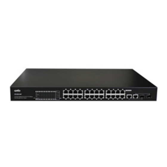
- Page 1 CERIO Corporation CS-2224-24P_A2 PoE CS-2000 Series 2 Combo Gigabit + 24 port 10/100Mbps Web Managed PoE+ Switch User’s Manual...
- Page 2 FCC Warning This device has been tested and found to comply with limits for a Class A digital device, pursuant to Part 2 and 15 of the FCC Rules. These limits are designed to provide reasonable protection against harmful interference when the equipment is operated in a commercial environment. This equipment generates, uses and can radiates radio frequency energy and, if not installed and used in accordance with the user’s manual, may cause interference in which case user will be required to correct the interference at his own expense.
-
Page 3: Table Of Contents
Introduction ............................5 Front Panel ..........................5 Rear Panel Layout ........................6 Connections ..........................6 Software Configuration ........................7 Example of Segment: (Windows 7) ....................7 System login username and password information ............. 11 Management ............................12 Authentication Configuration....................12 System IP Configuration ...................... - Page 4 10. Spanning Tree ........................... 44 10.1 STP Bridge Settings ......................44 10.2 STP Port Setting ........................45 11. Trunking (Link aggregation) ......................47 12. DHCP Relay Agent ........................... 49 12.1 DHCP Relay Agent ......................... 49 12.2 Relay Server ..........................50 12.3 VLAN MAP Relay Agent ......................
-
Page 5: Introduction
1. Introduction 1.1 Front Panel LED Indicators of 24 Port 10/100Mps + 2 giga Switch 1) Hardware Reset button, press and hold for approximately 10 seconds. Once all the LED lights begin to flash, release the button to reset to default 2) System operational LED light 3) Power LED light 4) Ethernet Status LED Light. -
Page 6: Rear Panel Layout
1.2 Rear Panel Layout 1) AC input (100-240V/AC, 50-60Hz) UL Safety) 1.3 Connections Switch/Hub to this 8 Port with 8 Port Fast Ethernet PoE Switch This switch provides automatic crossover detection functionality for any port. It is simple and friendly to up-link to another switch without crossover cable. xDSL RJ-45 Data and PoE Out Giga to Giga uplink... -
Page 7: Software Configuration
Power Device to this 24 Port with 24 Port Fast Ethernet PoE Switch and getting 48V power source through Cat. 5/6 cables Using Cat. 5/6 twisted-pair cable to connect Power Device to the port 1~24 of this switch, and then this switch will supply 48V power to Power Device over Cat. 5/6 twisted-pair cable. Please be noted Power Device should also comply with IEEE 802.3af/ IEEE802.3at. - Page 8 Step 2 : In the Network and Sharing Center page, click on the left side of “Change adapter setting” button Step 3 : In “Change adapter setting” Page, right click on Local LAN then select “Properties”...
- Page 9 Step 4 : In the “Properties” page, click the “Properties” button to open TCP/IP setting Step 5 : In Properties page for setting IP addresses, find “Internet Protocol Version 4 (TCP/IPv4)” and double click to open TCP/IPv4 Properties window Double click...
- Page 10 Step 6 : Select “Use the following IP address”, and fix in IP Address to: 192.168.2.X ex. The X is any number from 1 to 253 Subnet mask : 255.255.255.0 And Click "OK" to complete fixing the computer IP settings Step 7 : Open Web Browser Without a valid certificate, users may encounter the following problem in IE7 when they try to...
-
Page 11: System Login Username And Password Information
2.1 System login username and password information The CS-2224-24P web switch default IP is 192.168.2.200 Into the management page as follows, please enter Username and password Default IP Address: 192.168.2.200 Default Username and Password Management Account Root Account Username root Password... -
Page 12: Management
3. Management Authentication Configuration This page allows the user to change the user name and the password. Please click Management setup Authentication Configuration Administrator login username is always root and the password is allowed to be changed Username : Management account is “root” ... -
Page 13: System Ip Configuration
Click “Update” button to save your changes. Click Reboot button to activate your changes 3.2 System IP Configuration Here are the instructions for how to setup the local IP Address and Netmask. Please click Management setup System IP Configuration ... -
Page 14: System Time Setting(Ntp)
IP Address : The IP address of the system; default IP address is 192.168.2.200 IP Netmask : The Subnet mask of the system; default Netmask is 255.255.255.0 Gateway : Configure the network gateway address IP Configure: The administrator can manually setup the system IP address when ... -
Page 15: System Status
System Time: After confirming with the NTP server time proofreading, the system will display correct time. NTP Server Setting: Administrator can setup 2 IP for NTP Server. Administrator must configure the system gateway, so that the system can be connect internet to NTP server. - Page 16 MAC Address: MAC address of the display system Number of Ports: Display CS-2224-24P the Ethernet posts information Description: Provide description of the system. Firmware version: Show currently the CS-2224-24P of system software version and software date Set login Time out: set Idle Time(1~30 Minutes) ...
- Page 17 3.5 Reset to default Please click Management setup Reset to default Click Default button to reset back to the factory default settings and expect Successful loading message. Then, click Reboot button to activate. Recover switch system to default setting but excluding the IP address and Password.
-
Page 18: Firmware Update
3.6 Firmware Update Firmware is the main software image that system needs to respond to requests and to manage real time operations. Firmware upgrades are sometimes required to include new features or bugs fix. It takes around 2 minutes to upgrade due to complexity of firmware. To upgrade system firmware, click Browse button to locate the new firmware, and then click Upgrade button to upgrade. -
Page 19: Backup/Recovery
Do not interrupt during firmware upgrade including power on/off as this may damage system. 3.7 Backup/Recovery This function includes actions such as: backup current configuration, recovery prior configuration, configuration can be executed via this page. -
Page 20: Reboot Device
Backup: Click “Download” button to save the current configuration to a local disk. Recovery: Click “Browse” button to locate a configuration file to restore, and then click Update button to upload. Password: Enter system password. 3.8 Reboot Device This function allows user to restart system with existing or most current settings when changes are made. -
Page 21: Poe Control
4. PoE Control 4.1 PoE Status Administrator can monitor Power consumption / PoE Module Temperature and set Max available Power for PoE. Please click “PoE control” PoE Status... -
Page 22: Poe Setting
4.2 PoE Setting Administrator can enable / disable PoE Port, and can select Critical/High/Low for PoE priority, PoE port support Power Budget (Max to 36Watt). Please click PoE control PoE Setting Function: Status: Administrator can select enable or disable the PoE function. ... -
Page 23: Poe Power Delay
4.3 PoE Power Delay The function support PoE delay control. Administrator can set delay time by sec. Please click “PoE control” ”PoE Setting” Function Delay Mode: Administrator can select enable/disable the delay function. Delay time: Administrator can set delay time by sec.(Max.300 sec) ... -
Page 24: Poe Schedule
4.4 PoE Schedule Administrator can set schedule to control PoE on/off Please click “PoE control” “PoE Schedule”... - Page 25 Schedule on Port: Administrator can select an single port to set on/off schedule. Schedule Mode: Administrator can select enable or disable schedule of the single port. Schedule AM/PM: Select time for AM or PM Select all time: Select all-time in schedule list. ...
-
Page 26: Port Management
5. Port Management 5.1 Port Configuration Please click Port Management Port Configuration Function: Tx/Rx Ability: Administrator can select enable/disable for the transmission ability. Auto-Negotiation: Administrator can select enable/disable for the Auto-Negotiation. Speed: Administrator can select speed for 10M, 100M or 1G mode. ... -
Page 27: Port Mirroring
5.2 Port Mirroring Port mirroring function can mirror Rx/Tx traffic, Packet can mirror to Destination port and for analysis. Please click Port Management Port Mirroring Destination port: Administrator can select port 1~26 for destination port. Monitored Packets: Administrator can select Tx or Rx to monitor transmission. ... -
Page 28: Bandwidth Control
5.3 Bandwidth Control If the link speed of selected port is lower than the rate that you setting, this system will use the value of link speed as your setting rate. Please click Port Management Bandwidth Control Port No.: Administrator can select port 1 to port 26. ... -
Page 29: Broadcast Storm Control
2) The bandwidth resolution is 2048Kbps for port 25, port 26. (Actual Tx/Rx bandwidth=Rate value x 2048 Kbps, The rate value is 1~255.) Click “Save” to save the setting. 5.4 Broadcast Storm Control This value indicates the number of broadcast packet which is allowed to enter each port in one time unit. -
Page 30: Vlan Setting
6. VLAN Setting 6.1 VLAN Mode The VLAN function can change Port Based VLAN and Tag Based VLAN. System default is Port Based VLAN. Please click VLAN Setting VLAN mode Administrator can click “Change VLAN mode” button to tag VLAN mode. - Page 31 Tag: Insert port's tag for egress packets. Don’t Care: No change any egress packets. Remove Tag: Remove tag ID. 1. Link partner is a network interface card; it probably cannot recognize the VLAN tag. In this case, it is strongly recommended the network administrator to remove the VLAN tag of the corresponding port.
-
Page 32: Vlan Member Setting (Tag Based)
6.2 VLAN Member Setting (Tag Based) Administrator can set VLAN Member for Port or Tag VLAN, if VLAN mode used port VLAN function, the VLAN Member will display Port based VLAN function, if VLAN mode used Tag VLAN function, the VLAN member will display Tag VLAN function. Please click VLAN Setting ... - Page 33 : If administrator creates group, the Dropdown opens up created groups Delete: Administrator can delete group. Update: After completing group modifications, click Update to finalizes changes LoadDefault: Delete all groups. Tag Based VLAN Function Dropdown: Administrator can select the created groups. ...
-
Page 34: Multi To 1 Setting
6.3 Multi to 1 Setting The original setting of the VLAN Group will be cleared and replaced by this special structure if you enable this function. On the other hand, If you set the VLAN Group again, this special structure will be cleared and replaced by your newest setting. -
Page 35: Per Port Counter
Service: Administrator can select enable/disable the function. Destination Port No.: Choose a port of Destination Port”. Current Setting: Display currently set of Destination port No. information Disable Port: Choose the ports will separate oneself from to destination. ... - Page 36 Counter Mode Selection Transmit Packet & Receive Packet: Display 1 to 26 ports of Transmit Packet and Receive Packet information. Collision Count & Transmit Packet: Display 1 to 26 ports of Collision Count and Transmit Packet information. Drop Packet & Receive Packet: Display 1 to 26 ports of Drop Packet and Receive Packet ...
-
Page 37: Qos Setting
8. QoS Setting Quality of Service (QoS) prioritizes network traffic and manages available bandwidth so that the most important traffic goes first. QoS is implemented as rules or policies that prioritize packets, optionally change information in the packet header, and assign them to outbound port queues based on their priority. -
Page 38: Port, 802.1P, Ip/Ds Based
First-in-First-Out: The first receiving packet will be firstly transmitted. All-High-before-Low: All packets will be assigned to either Q2 (high) priority queue or Q1 (low) priority queue. Weight-Round-Robin: set the ratio of the transmitting packet for the low priority to high ... -
Page 39: Tcp/Udp Port Based
Enable is High Priority 8.3 TCP/UDP Port Based Please click QoS Setting TCP/UDP Port Based Base on different protocol, you can choose four different types of Class of Service for each TCP/UDP port number -First-in-First-out, Discard, High Priority or Law Priority to control the incoming packet. - Page 40 The Class of Service for TCP/UDP port number allows the network administrator to assign the specific application to a priority queue. F-I-F-O: The incoming packet will be forwarded in first-in-first-out scheme. Discard: The incoming packet will be discarded at the source port. ...
-
Page 41: Security
9. Security 9.1 MAC address Binding Set special MAC address to activate on the selected port Please click Security MAC Address Binding If you setting and enable the binding MAC address in access control list, The port only allow MAC address on the access control list. -
Page 42: Service Protocol Filter
9.2 Service Protocol Filter You can enable or disable this function of per port. Please click Security Service Protocol Filter Function: setting Disable / Enable the function. Port Filtering Rule: The outgoing packet with selected protocol will be either forwarded or ... - Page 43 "Negative" means the selected protocol will be dropped and other protocols will be forwarded. "Positive" means the selected protocol will be forwarded and other protocol will be dropped. Protocol: choose protocols which you want. Secure WAN Port: choose secure ports which you want. ...
-
Page 44: Spanning Tree
Spanning Tree Spanning Tree Protocol(STP) allows only one active path at a time between any two network devices (this prevents the loops) but establishes the redundant links as a backup if the initial link should fail. If STP costs change, or if one network segment in the STP becomes unreachable, the spanning tree algorithm reconfigures the spanning tree topology and reestablishes the link by activating the standby path. -
Page 45: Stp Port Setting
STP Mode: choose “Disable”, “STP” or “RSTP” Bridge Priority: Set the priority of the Bridge. Hello Time: Provides the time period between root bridge configuration messages. Max Age: Indicates when the current configuration message should be deleted. ... - Page 46 Port No.: Choose Port 1 ~ Port 26 Priority: Setting 0~ 240 RPC: The RPC= Root Path Cost: 0 = AUTO. When the loop is found, the STP/RSTP will calculate the cost of its path. STP Port Status...
-
Page 47: Trunking (Link Aggregation)
11. Trunking (Link aggregation) Link aggregation can aggregate multiple Ethernet ports together to form a logical aggregation group. To upper layer entities, all the physical links in an aggregation group are a single logical link. Link aggregation is designed to increase bandwidth by implementing outgoing/incoming load sharing among the member ports in an aggregation group. - Page 48 Member: Choose link group port. State: Choose Enable / Disable the link group function. Type: The IEEE 802.3ad Link Aggregation Control Protocol (LACP) enables the dynamic aggregation of physical links and The Link Aggregation Control Protocol (LACP) is defined in IEEE 802.3ad.
-
Page 49: Dhcp Relay Agent
12. DHCP Relay Agent 12.1 DHCP Relay Agent Since DHCP clients request IP addresses via broadcast messages, the DHCP server and clients must be on the same subnet. Therefore, a DHCP server must be available on each subnet. It is not practical. DHCP relay agent solves the problem. -
Page 50: Relay Server
DHCP Relay Option 82 State: The DHCP Information option (Option 82) is commonly used in metro or large enterprise deployments to provide additional information on “physical attachment” of the client. Option 82 is supposed to be used in distributed DHCP server/relay environment, where relays insert additional information to identify the client’s point of attachment. -
Page 51: Vlan Map Relay Agent
Click “Save” to confirm and finish the setting. 12.3 VLAN MAP Relay Agent Please click DHCP Relay Agent VLAN MAP Relay Agent... -
Page 52: Other Setting
VLAN ID: Please Enter VLAN 10 number. Map Server IP: If setting the completed of Relay Server function, The Map server IP you can select IP address. Click “Save” to confirm and finish the setting. 13. Other Setting The function you can setting Aging time / VLAN Striding / and IGMP Snooping etc. - Page 53 Output Queue Aging Time: Choose Aging time is 200/400/600/800ms or disable etc. The output queue aging function allows the administrator to select the aging time of a packet stored in the output queue. A packet stored in the output queue for a long time will lower the free packet buffer, resulting in the poor utilization of the buffer and the poor switch performance.
-
Page 54: Snmp Setting
IGMP Snooping V1 & V2: You can choose IGMP Snooping disable or enable function. After enable IGMP, will use both V1 and V2 function. If enable IGMP Snooping function, you can choose disable or enable the IGMP Leave Packet. Mainly allows Leave packet will be forwarded to IGMP router ports. - Page 55 Community Names: Only requests from computers in the list of community names will be accepted. SNMP default communities are: public=Read / Write Click “Save” to confirm and finish the setting. System Description: Enter the System description. System Contact: Enter the System Contact. ...
-
Page 56: Logout
Enable Trap Server: The function can select Trap Server of Enable or Disable. Trap Server Address: Enter Trap Server address. Trap Server Status: Display Trap Server Status information. Click “Save” to confirm and finish the setting. 15. Logout Click “Logout”...
Need help?
Do you have a question about the CS-2000 Series and is the answer not in the manual?
Questions and answers