Cerio CS-2000 Series User Manual
8 port 10/100/1000m gigabit web managed poe+ switch (150watt power)
Hide thumbs
Also See for CS-2000 Series:
- User manual (20 pages) ,
- User manual (56 pages) ,
- User manual (70 pages)

Related Manuals for Cerio CS-2000 Series


Summary of Contents for Cerio CS-2000 Series
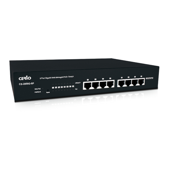
- Page 1 CERIO Corporation CS-2008G-8P PoE CS-2000 Series - 8 Port 10/100/1000M Gigabit Web Managed PoE+ Switch ( 150Watt Power ) User’s Manual V2.0b...
- Page 2 FCC Warning This device has been tested and found to comply with limits for a Class A digital device, pursuant to Part 2 and 15 of the FCC Rules. These limits are designed to provide reasonable protection against harmful interference when the equipment is operated in a commercial environment. This equipment generates, uses and can radiates radio frequency energy and, if not installed and used in accordance with the user’s manual, may cause interference in which case user will be required to correct the interference at his own expense.
-
Page 3: Table Of Contents
Introduction ........................... 4 Front Panel ......................... 4 Rear Panel Layout ......................4 Software Configuration ......................... 5 Example of windows PC Setup..................5 System login ........................8 System ............................9 Management ..........................10 VLAN............................. 11 Trunking ............................12 Mirror ............................13 QoS ............................... -
Page 4: Introduction
1. Introduction 1.1 Front Panel 1) MAX PoE (budget expended) LED light. 2) Power and System status LED light. 3) Reset to default button. 4) 8 PoE Ports and Ethernet status LED light. 5) 8 Gigabit Ethernet Ports. 1.2 Rear Panel Layout ... -
Page 5: Software Configuration
2. Software Configuration CS-2008G-8P supports web-based configuration. Please refer to the following steps 2.1 Example of windows PC Setup. The following setup uses a Windows PC, user OS may vary Step 1 : Please click on the computer icon in the bottom right window, and click “Open Network and Internet settings”... - Page 6 Step 3 : In “Change adapter options” Page. Please find Ethernet (Local LAN) and Click the right button on the mouse and Click “Properties” Step 4 : In Properties page to setting IP address, please find “Internet Protocol Version 4 (TCP/IPv4)” and double click or click “OK”...
- Page 7 Step 5: Select “Use the following IP address”, and fix in IP Address to: 192.168.2.X ex. The X is any number from 1 to 253 Subnet mask : 255.255.255.0 And Click "OK" to complete fixing the computer IP settings Step 6: Open Web Browser Launch as web browser to access the web management interface of system by entering the default IP Address, http://192.168.2.254, in the URL field, and then press Enter.
-
Page 8: System Login
2.2 System login The CS-2008G-8P web switch default IP is 192.168.2.200 Into the management page as follows, please enter Username and password Default IP Address: 192.168.2.200 Default Username and Password Management Account Password default After Login page will display system information. V2.0b... -
Page 9: System
3. System The page administrator can monitor switch information and modify network IP / mask. Model Name: Display switch model name. Device Name: Administrator can modify the system name. Firmware Version: Display system firmware version. Build Date: Display firmware release date. ... -
Page 10: Management
4. Management This page administrator can reboot the system or reset the system to default settings. Users can also backup or restore device settings, and also upgrade firmware from this page. System Reset to default: Administrator can click the button to reset system default. ... -
Page 11: Vlan
5. VLAN The VLAN function administrator can set IEEE 802.1q Tag Based VLAN or Port Based VLAN. System default is tag based VLAN. IEEE 802.1Q VLAN PVID: Administrator can set Port tag VLAN ID 802.1Q VLAN: Administrator can set tag number for 802.1Q VLAN. ... -
Page 12: Trunking
6. Trunking The trunking function support 802.3ad (LACP, Link Aggregation Control Protocol) Link Aggregation Control Protocol (LACP) can aggregate multiple Ethernet ports together to form a logical aggregation group. To upper layer entities, all the physical links in an aggregation group are a single logical link. -
Page 13: Mirror
7. Mirror Port mirroring function can mirror Ingress/Egress traffic, the packet can mirror to Destination port and for analysis Enable Mirror: Administrator can check to start mirror function Mirror To: Administrator can mirror traffic to select post. List: Administrator can selected mirror type by ingress or Egress ... - Page 14 Select QoS Type Disable QoS: Administrator can disable QoS function. Port-Based QoS: Administrator can use Port-Based mode to traffic management. IEEE 802.1q QoS: Administrator can use IEEE 802.1q mode to traffic management. Port-Based QoS: Administrator can set Queue (weight) QoS by Port. Queue0 is Low Priority, Queue3 is High Priority.
-
Page 15: Rate Limiting
IEEE 802.1q QoS Administrator can set Queue (weight) QoS by Tag VLAN. Queue0 is Low Priority, Queue3 is High Priority. 9. Rate Limiting The rate limiting function can be configured to limit the rate of traffic received on a particular interface. -
Page 16: Loop Detection / Prevention
Loop Detection / Prevention Loop detection / Prevention can be used in a network topology to prevent or detect Layer 2 loops that occur due to misconfigurations. When occur a loop, Administrator can go to user manual “System” (section 3.) to monitor loop status, and tick off Loop Unlock for desired ports. -
Page 17: Igmp Snooping
IGMP Snooping IGMP snooping is the process of listening to Internet Group Management Protocol (IGMP) network traffic. The feature allows a network switch to listen in on the IGMP conversation between hosts and routers. By listening to these conversations the switch maintains a map of which links need which IP multicast streams. -
Page 18: Poe
The function can monitor PoE used power status / Module Temperature and PoE voltage status. Administrators can control PoE usage through the per port On/Off option. POE Global Settings: The function can monitor PoE used power status / Module Temperature and PoE voltage status. -
Page 19: Password
Password Administrator can change the Switch login password on this page. The default login password is default Logout Clicking the logout button will log the administrator out of the management page. V2.0b... - Page 20 V2.0b...
Need help?
Do you have a question about the CS-2000 Series and is the answer not in the manual?
Questions and answers