
Related Manuals for Wilo American-Marsh Pumps HH 380 Series


Summary of Contents for Wilo American-Marsh Pumps HH 380 Series
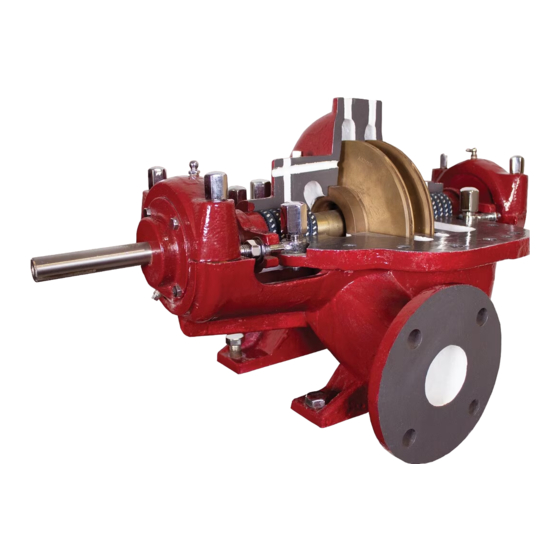
- Page 1 380 Series HH Two-Stage Horizontal Split Case Pumps Installation and Operating Manual IOM_380 Series_1021...
-
Page 2: Table Of Contents
CONTENTS Page # SAFETY CONSIDERATIONS ..............................4 DANGER ..................................... 4 WARNING ................................... 4 CAUTION ..................................... 4 PUMP IDENTIFICATION ................................ 5 MANUFACTURER ................................5 TYPE OF PUMP .................................. 5 DATE OF MANUFACTURE ..............................5 INSTALLATION, OPERATION & MAINTENANCE MANUAL IDENTIFICATION ............... 5 NAMEPLATE INFORMATION ............................. - Page 3 MAINTENANCE OF PUMP DUE TO FLOOD DAMAGE ....................21 DISASSEMBLY ................................. 21 PURGE GREASE BEARING HOUSING PORTION OF ROTATING ASSEMBLY ............22 OPTIONAL RING OILED BEARING HOUSING PORTION OF ROTATING ASSEMBLY ..........22 FLUID PORTION OF ROTATING ASSEMBLY ......................23 RE-ASSEMBLY .................................
-
Page 4: Safety Considerations
Do not run the equipment dry or start the pump without SAFETY CONSIDERATIONS the proper prime (casing flooded). The American-Marsh HH multistage split case pump has been designed and manufactured for safe operation. In Never operate the pump for more than a short interval order to ensure safe operation, it is very important that with the discharge valve closed. -
Page 5: Pump Identification
American-Marsh Pumps, LLC MAINTENANCE MANUAL IDENTIFICATION 550 E. South St. Prepared: October, 2021 Edition: 01 Date Collierville, TN 38017 Revision: A Wilo Brand of Revision: United States of America 10-01-21 TYPE OF PUMP The American-Marsh HH multistage split case pump is a horizontal, two stage, axially split centrifugal pump. -
Page 6: Warranty
In case of doubt, contact the manufacturer. WARRANTY HANDLING AND TRANSPORT American-Marsh Pumps guarantees that only high quality materials are used in the construction of our pumps and that machining and assembly are carried out METHOD OF TRANSPORT to high standards. The pump must be transported in the horizontal position The pumps are guaranteed against defective materials INSTALLATION... -
Page 7: Long-Term Storage
flange faces, and the impeller surface are Every three months, the shaft should be rotated sprayed with Calgon Vestal Labs RP-743m, or approximately 10 revolutions. equal. Exposed shafts are taped with Polywrap. e. Flange faces are protected with plastic covers INSTALLATION &... -
Page 8: Recommended Procedure For Base Plate Installation & Final Field Alignment
11. Both horizontal and vertical alignment are again final checked as is the coupling spacer gap. RECOMMENDED PROCEDURE FOR BASE PLATE INSTALLATION & FINAL FIELD ALIGNMENT NEW GROUTED BASE PLATES 1. The pump foundation should be located as close to the source of the fluid to be pumped as practical. -
Page 9: Existing Grouted Base Plates
are centered in the driver feet holes. If not, no more than 0.002 in (0.05mm) parallel, re-center the fasteners and perform a and 0.0005 in/in (0.0005 mm/mm) angular preliminary alignment to the above misalignment. tolerances by shimming under the motor for 8. -
Page 10: Suction Piping
with expansion joints to prevent pipe strain. Do not install expansion joints next to the pump or in any way that would cause a strain on the pump resulting from system pressure changes. It is usually advisable to increase the size of both suction and discharge pipes at the pump connections to decrease the loss of head from friction. - Page 11 suction nozzle in order to maintain pipe velocities less the discharge line (See “Valves in Discharge Piping” than 5 feet/second. below). b. When foot valves are used, or where there are other Suction piping should be short in length, as direct as possibilities of “water hammer,”...
-
Page 12: Pump And Shaft Alignment Check
Seal and seal support system must be installed and operational as specified by the seal manufacturer. Mechanical seals are preferred over packing on some applications because of better sealing qualities and longer service-ability. When fluid velocity in the pipe is high, for example, 10 ft/s (3 m/s) or higher, a rapidly closing discharge valve Leakage is eliminated when a seal is properly installed, can cause a damaging pressure surge. -
Page 13: Bearing Lubrication
Grease lubrication, when compatible with the pumpage, from animal or vegetable oils are not recommended due may be used. In non-abrasive applications the pumpage to the danger of deterioration and forming of acid. Do itself may be sufficient to lubricate the packing without not use graphite. -
Page 14: Pump Operation
done by other methods such as foot valves, ejectors, or The coupling should be installed as advised by the by manually filling the casing and suction line. coupling manufacturer. Pumps are shipped without the spacer installed. If the spacer has been installed to ENSURING PROPER NPSH facilitate alignment, then it must be removed prior to Net Positive Suction Head –... -
Page 15: Starting The Pump And Adjusting Flow
valve a slight amount. This will allow any 60 Hz 50 Hz entrapped air to escape and will normally allow Minimum Minimum the pump to prime, if the suction source is above Pump Size Flow Flow the pump. When a condition exists where the (% of BEP) (% of BEP) suction pressure may drop below the pump’s... -
Page 16: Operation In Sub-Freezing Conditions
A rapidly closing discharge valve can cause a damaging pressure surge. A dampening arrangement should be provided in the piping. OPERATION IN SUB-FREEZING CONDITIONS When using the pump in sub-freezing conditions where the pump is periodically idle, the pump should be properly drained or protected with thermal devices which will keep the liquid in the pump from freezing. - Page 17 PROBLEM POSSIBLE CAUSE RECOMMENDED REMEDY Problem #1 Recalculate NPSH available. It must be Pump not reaching design flow Insufficient NPSH . (Noise may not be greater than the NPSH required by pump rate. present) at desired flow. If not, redesign suction piping, holding number of elbows and number of planes to a minimum to avoid adverse flow rotation as it approaches...
- Page 18 PROBLEM POSSIBLE CAUSE RECOMMENDED REMEDY Cont. Problem #3.0 Refer to recommended remedy under No discharge or flow Entrained air. Air leak from Problem #1.0, atmosphere on suction side. Item #1.3. Refer to recommended remedy under Plugged impeller, suction line or casing Problem #1.0, which may be due to a fibrous product Item #1.9.
- Page 19 PROBLEM POSSIBLE CAUSE RECOMMENDED REMEDY Cont. Problem #6.0 1. Correct the source of vibration. Excessive noise from power False brinelling of bearing identified 2. Where bearings are oil lubricated and end. again by either axial or circumferential employed in units that may be out of indentations usually caused by service for extended periods, the drive vibration of the balls between the races...
- Page 20 PROBLEM POSSIBLE CAUSE RECOMMENDED REMEDY Cont.: Problem #6.0 1. Be sure the lubricant is clean. Excessive noise from power Bearing damage due to improper 2. Be sure proper amount of lubricant is end. lubrication, identified by one or more of used.
-
Page 21: Maintenance
Next, inspect the stuffing box, and clean out any foreign MAINTENANCE matter that might clog the box. Mechanical seals should be cleaned and thoroughly flushed. PREVENTIVE MAINTENANCE Couplings should be dismantled and thoroughly cleaned. The following sections of this manual give instructions on Any pump that is properly sealed at all joints and how to perform a complete maintenance overhaul. -
Page 22: Purge Grease Bearing Housing Portion Of Rotating Assembly
3. Close all valves on auxiliary equipment and shaft (#41D). Discard the outboard bearing piping, then disconnect all auxiliary piping. (#81N). 4. Decontaminate the pump as necessary. If 16. Remove the outboard shaft bushing (#45A) from American-Marsh pumps contain dangerous the shaft (#41D). -
Page 23: Fluid Portion Of Rotating Assembly
31. Remove the four bearing cap capscrews from 43. Remove the inboard shaft sleeve (#42C), the inboard/inboard bearing housing cap (#97N). inspect and replace if necessary. Remove the Remove the inboard/inboard bearing housing inboard case wear ring (#15A). cap (#85N). Discard the inboard/inboard bearing 44. -
Page 24: Re-Assembly
exposure to possible contamination. After removing the packaging they should only come in contact with clean RE-ASSEMBLY hands, fixtures, tools and work surfaces. BEARING INSTALLATION The chart shown in Figure 9 gives the SKF part numbers Mounting of bearings on shafts must be done in a clean for bearings in American-Marsh HH pumps. -
Page 25: Fluid Portion Of Rotating Assembly
FLUID PORTION OF ROTATING ASSEMBLY 1. Wipe over the shaft (#41D) with clean light oil. Place impeller key (#24A) into shaft keyway. Check impellers (#11H & 11J) for correct ° ° Do not exceed 248 F (120 C). Temperatures in excess rotation (See Figure 10) and place the inboard of this will permanently damage ball bearing. -
Page 26: Ring Oiled Bearing Housing Portion Of Rotating Assembly
capscrews from the outboard bearing housing bearing is seated at the bottom of the bearing cap (#85N) location. housing (#8sN). 13. Heat the inboard ball bearing (#81P) to 47. Heat the outboard ball bearing (#81N) and approximately 212°F (100°C) using a bearing bearing housing (#82N) to approximately 212°F hot plate or lubricating oil bath. - Page 27 bearing housing cap (#85N) to the bearing housing. Install the four bearing cap capscrews from the inboard/inboard bearing housing cap BOLT SIZE TIGHTENING TORQUE (#85N) location. Metric Standard Lbf ft 28. Place the casing gaskets (#353A) on the pump casing half (#1A). Pull the gaskets tight against 4 mm 5/32”...
-
Page 28: Installing Stuffing Box Packing
Stuffing Box Information INSTALLING STUFFING BOX PACKING Pump Model Bore Depth Packing Refer to Figure 12 for number of packing rings required 1.5x2.5-8 HH 2.250 2.875 8 - 3/8" SQ by pump model. 1.5x2.5-10 HH 2.250 2.875 8 - 3/8" SQ 2x3-8 HH 2.250 2.875... -
Page 29: American-Marsh Hh Maintenance Instructions Bearing Housing Oil Seals (Labyrinth Type) Inpro/Seal Vbxx Bearing Isolators
VBXX to ensure a perfect seal with the housing bore. APPENDIX A 2. Repair or replacement of the seals is only necessary when excessive oil leakage is AMERICAN-MARSH HH MAINTENANCE evident. However, if for any other reason, the INSTRUCTIONS BEARING HOUSING OIL bearing housing is to be disassembled or the pump shaft removed, it is recommended that the ®... -
Page 30: Trico Oiler Instructions
APPENDIX B TRICO OILER INSTRUCTIONS LUBRICATOR RE-INSTALLATION 1. Check the center line of the lubricator and confirm that it is parallel with the bearing housing (Figure 14 & 15). Use spirit level if possible. Should a condition as in Figure 16 occur, the lubricator will not function properly. - Page 31 Figure 19 – HH Packing/Seal Chamber Details Sleeve Hinge Bolt Pump Model Diameter Diameter 1.5x2.5-8 HH 2.250 0.500 2.875 2.250 4.500 1.813 1.5x2.5-10 HH 2.250 0.500 2.875 2.250 4.500 1.813 2x3-8 HH 2.250 0.500 2.875 2.250 4.500 1.813 2x3-10 HH 2.625 0.500 2.875...
- Page 32 FIGURE 20 – HH Sectional Drawing HH Sectional Drawing Item Num. Item Num. Item Description Item Description Number Req. Number Req. Casing Cap, Housing, Outboard Impeller, 1 Stage Cap, Housing, Inboard Impeller, 2 Stage Spacer, Bearing Ring, Casing Wearing 87P* Spacer, Bearing Pin, Dowel, Casing Ring Ring, Oil...
Need help?
Do you have a question about the American-Marsh Pumps HH 380 Series and is the answer not in the manual?
Questions and answers