
Related Manuals for Wilo Helix2.0-VE


Summary of Contents for Wilo Helix2.0-VE
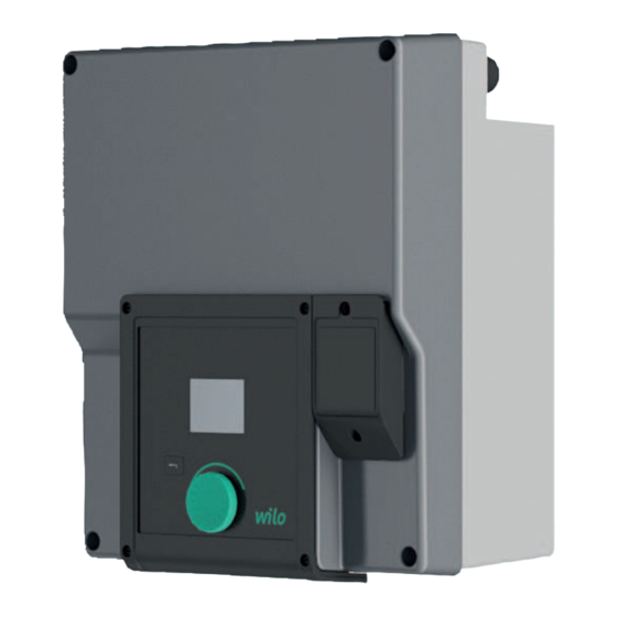
- Page 1 Pioneering for You Drive for Wilo-Helix2.0-VE / Wilo-Medana CH3-LE en Installation and operating instructions · 4254674 • Ed.01/2022-06...
- Page 3 English ..........................
-
Page 4: Table Of Contents
Pump operation.............. 30 10 Control settings................ 36 10.1 Control functions .............. 37 10.2 Selection of a control ............ 38 10.3 Switch off the pump............ 45 10.4 Configuration storage/data storage......... 46 11 Monitoring functions ............... 46 Installation and operating instructions • Drive for Wilo-Helix2.0-VE / Wilo-Medana CH3-LE • Ed.01/2022-06... -
Page 5: General
Contents, of any kind, must not be reproduced, distributed, or used for purposes of com- petition and shared with others. Wilo reserve the right to change the listed data without notice and not be liable for tech- Subject to change nical inaccuracies and/or omissions. -
Page 6: Personnel Qualification
The operator must confirm and ensure the field of authority, the competence and the monitoring of the person- Installation and operating instructions • Drive for Wilo-Helix2.0-VE / Wilo-Medana CH3-LE • Ed.01/2022-06... -
Page 7: Electrical Work
Safety helmet (when using lifting equipment) – • Only use legally specified and approved lifting gear. • Select lifting gear based on the available conditions (weather, attachment point, load, etc.). Installation and operating instructions • Drive for Wilo-Helix2.0-VE / Wilo-Medana CH3-LE • Ed.01/2022-06... -
Page 8: Installation / Dismantling
After completing work, reattach all safety and monitoring devices and check that they function properly. Other responsibilities • Provide installation and operating instructions in a language which the personnel can understand. Installation and operating instructions • Drive for Wilo-Helix2.0-VE / Wilo-Medana CH3-LE • Ed.01/2022-06... -
Page 9: Intended Use And Misuse
Industrial water • Closed cooling circuits • Heating • Washing systems • Irrigation Installation within a building: Drive is to be installed in dry, well-ventilated, frost-proof rooms. Installation and operating instructions • Drive for Wilo-Helix2.0-VE / Wilo-Medana CH3-LE • Ed.01/2022-06... -
Page 10: Misuse
Arrangement of the main components according to Fig.1, Fig. 2 and Fig. 3 of the table "Ar- rangement of the main components": Fig. 1: Main compontents Installation and operating instructions • Drive for Wilo-Helix2.0-VE / Wilo-Medana CH3-LE • Ed.01/2022-06... - Page 11 The display can be rotated in 90° steps as required. (See chapter "Electrical connec- tion"). Electronic module An unobstructed and free air flow must be ensured around the electric fan. (See chapter on "Installation") Installation and operating instructions • Drive for Wilo-Helix2.0-VE / Wilo-Medana CH3-LE • Ed.01/2022-06...
-
Page 12: Technical Data
OVC I II + S PD/MOV Overvoltage Category I II + S urge Protective Device/ Metal Oxide Varistor Protection function control termin- SELV, galvanically isolated Installation and operating instructions • Drive for Wilo-Helix2.0-VE / Wilo-Medana CH3-LE • Ed.01/2022-06... -
Page 13: Scope Of Delivery
In the case of 3~ input power supply with motor powers of 2.2 and 3 kW, EMC irregularit- ies can occur under unfavourable circumstances when used in residential environments (C1) with low electrical power in the conducted range. In this case, please contact WILO SE so that together we can find a quick and suitable shutdown measure. -
Page 14: Permitted Installation Positions And Change Of The Arrangement Of Components Before The Installation
The component arrangement concerning the pump housing is pre-assembled as a factory setting and can be changed at the operating location if required. This may be necessary, for example, in the following cases: Installation and operating instructions • Drive for Wilo-Helix2.0-VE / Wilo-Medana CH3-LE • Ed.01/2022-06... -
Page 15: Preparing The Installation
. Never transport the entire pump with the transport lugs attached to the motor housing. . Never use the transport lugs attached to the motor housing to separate or pull out the motor unit. Installation and operating instructions • Drive for Wilo-Helix2.0-VE / Wilo-Medana CH3-LE • Ed.01/2022-06... -
Page 16: Double Pump Installation
See chapter "double pump operation". The measuring points of the pressure sensor must be on discharge side of the double-pump system in the common collector pipe. Fig. 6: Installation and operating instructions • Drive for Wilo-Helix2.0-VE / Wilo-Medana CH3-LE • Ed.01/2022-06... -
Page 17: Installation And Position Of Additional Sensors To Be Con
2 . .. 1 0 V • 0 . .. 2 0mA • 4 . .. 2 0mA The cable connection should be connected to analogue input 1. Installation and operating instructions • Drive for Wilo-Helix2.0-VE / Wilo-Medana CH3-LE • Ed.01/2022-06... -
Page 18: Electrical Connection
Water on the upper part of the electronic module can enter the elec- tronic module when it is opened. Before opening, remove water, e.g. on the display, by wiping it off com- pletely. Avoid water penetration in general! Installation and operating instructions • Drive for Wilo-Helix2.0-VE / Wilo-Medana CH3-LE • Ed.01/2022-06... - Page 19 Make sure that a gasket is fitted between the threaded cable gland and the cable bushing. The combination of threaded cable gland and cable bushing must be made according to the table "Cable connections": Installation and operating instructions • Drive for Wilo-Helix2.0-VE / Wilo-Medana CH3-LE • Ed.01/2022-06...
- Page 20 4, 5, 6 4 (Fig. 16) (Bus communication) Electrical connection of 4 (Fig. 9) the fan assembled at the factory (24 V D C) Table 4: Cable connections Installation and operating instructions • Drive for Wilo-Helix2.0-VE / Wilo-Medana CH3-LE • Ed.01/2022-06...
- Page 21 They can be opened with a screwdriver type slot SFZ 1 – 0 .6 x 0 .6 m m. Length of cable to strip The stripping length of the cables for the terminal connection is 8.5 m m . .. 9 .5 mm. Installation and operating instructions • Drive for Wilo-Helix2.0-VE / Wilo-Medana CH3-LE • Ed.01/2022-06...
- Page 22 • 4 – 2 0 m A Dielectric strength: 30 V D C / 2 4 V A C Power supply: 24 V DC: maximum 50 mA Installation and operating instructions • Drive for Wilo-Helix2.0-VE / Wilo-Medana CH3-LE • Ed.01/2022-06...
-
Page 23: Mains Connection
NOTICE It is preferable to switch on or off the pump with the digital input (Ext. Off) instead of the main power supply. Installation and operating instructions • Drive for Wilo-Helix2.0-VE / Wilo-Medana CH3-LE • Ed.01/2022-06... - Page 24 Fuse on mains side: max. 25 A Circuit breaker The use of a circuit breaker is recommended NOTICE Circuit breaker trigger characteristic: B Overload: 1.13-1.45 x I Short-circuit: 3-5 x Inom Installation and operating instructions • Drive for Wilo-Helix2.0-VE / Wilo-Medana CH3-LE • Ed.01/2022-06...
-
Page 25: Connection Of Ssm / Sbm
If pressure sensor is connected carry out the cable assignment as follows: Cable wire Terminal Function +24 V +24 V Signal Ground Table 6: Connection; pressure sensor cable Installation and operating instructions • Drive for Wilo-Helix2.0-VE / Wilo-Medana CH3-LE • Ed.01/2022-06... -
Page 26: Wilo Net Connection
For details on connection, see the detailed instructions at www.wilo.com! In order to establish the Wilo Net connection, the three Wilo Net terminals (H, L, GND) must be wired with a communication line from pump to pump. Incoming and outgoing cables are clamped in a terminal. -
Page 27: Installation Of Cif Module
CIF modules (accessories) are used for communication between pumps and building man- agement systems. CIF modules are plugged into the electronic module (Fig. 1 6, item 4 ) Installation and operating instructions • Drive for Wilo-Helix2.0-VE / Wilo-Medana CH3-LE • Ed.01/2022-06... -
Page 28: Commissioning
• For double pumps in common collector pipe applications in which the electronic mod- ules are connected to each other through the Wilo Net, only the main pump also requires a CIF module. NOTICE When using the Ethernet CIF module, it is recommended to use the "con- nection M12 RJ45 CIF Ethernet"... -
Page 29: Description Of The Operating Elements
Return to the main menu (press and hold 1 x , > 2 s econds). Switches the key lock (*) on or off (> 5 s econds) when pressing the oper- ating button. Table 8: Description of operating elements Installation and operating instructions • Drive for Wilo-Helix2.0-VE / Wilo-Medana CH3-LE • Ed.01/2022-06... -
Page 30: Pump Operation
Pressing the button again opens the home screen on the display and the pump can be operated from the main menu. Installation and operating instructions • Drive for Wilo-Helix2.0-VE / Wilo-Medana CH3-LE • Ed.01/2022-06... - Page 31 After selecting the language, the initial settings menu is exited. The pump changes to the main menu. The pump runs in the factory setting. NOTICE Universal means that a neutral number code is displayed instead of lan- guage. Installation and operating instructions • Drive for Wilo-Helix2.0-VE / Wilo-Medana CH3-LE • Ed.01/2022-06...
- Page 32 Yellow frame: You have pressed the operating button to open the setpoint editor and change the value. Active influences Display of influences on set control mode. E.g. EXT. O FF. You can display up to four active influences Installation and operating instructions • Drive for Wilo-Helix2.0-VE / Wilo-Medana CH3-LE • Ed.01/2022-06...
- Page 33 The following table lists Active Influences “Flow Related” indicated on the Home Screen: Symbol Displayed icon Description (from h ighest to l owest priority) Zero Flow Detection STOP Zero flow detected, pump stopped (off) Installation and operating instructions • Drive for Wilo-Helix2.0-VE / Wilo-Medana CH3-LE • Ed.01/2022-06...
- Page 34 The highlighted setting is changed by turning the operating button right or left. The setting is confirmed by pressing the operating button. The focus returns to the menu you opened. Installation and operating instructions • Drive for Wilo-Helix2.0-VE / Wilo-Medana CH3-LE • Ed.01/2022-06...
- Page 35 Communication status – a CIF module has been installed and is active. Pump in control mode, monitoring and control by building automation available. Table 11: Potential data displayed in the status area Installation and operating instructions • Drive for Wilo-Helix2.0-VE / Wilo-Medana CH3-LE • Ed.01/2022-06...
-
Page 36: Control Settings
CIF module 1.1.10 Substitute setpoint 1.1.11 No-flow stop: ON/OFF 1.1.12 No-flow stop: limit 1.1.13 Zero-flow test: ON/OFF 1.1.14 Zero-flow test: delay 1.1.15 Pump ON/OFF Switched OFF Switched ON Installation and operating instructions • Drive for Wilo-Helix2.0-VE / Wilo-Medana CH3-LE • Ed.01/2022-06... -
Page 37: Control Functions
30 % to 100 %). Constant speed (n-c / factory setting) The speed of the pump is kept at a set constant speed. User-defined PID control Installation and operating instructions • Drive for Wilo-Helix2.0-VE / Wilo-Medana CH3-LE • Ed.01/2022-06... -
Page 38: Selection Of A Control
PID control PID control The following basic control modes are available: Control modes > Variable differential pressure ∆p-v > Constant differential pressure ∆p-c > Constant speed n-c Installation and operating instructions • Drive for Wilo-Helix2.0-VE / Wilo-Medana CH3-LE • Ed.01/2022-06... - Page 39 When confirming the "Emergency operating mode" menu item, you can choose between pump OFF and pump ON. When selecting Pump ON, another menu item “Emergency operat- ing speed” appears. The emergency operating speed can be set here. Installation and operating instructions • Drive for Wilo-Helix2.0-VE / Wilo-Medana CH3-LE • Ed.01/2022-06...
- Page 40 When confirming the " No-flow stop " menu item, you can choose between switch OFF and switch ON. When selecting switch ON, another menu item “No-flow stop limit” ap- pears. The flow limit can be set here. Installation and operating instructions • Drive for Wilo-Helix2.0-VE / Wilo-Medana CH3-LE • Ed.01/2022-06...
- Page 41 "substitute setpoint" appears. A fixed setpoint can be specified here, which is used for the control in the event of a failure of the setpoint source (e.g. cable break at the analogue in- put, no communication with the CIF module). Installation and operating instructions • Drive for Wilo-Helix2.0-VE / Wilo-Medana CH3-LE • Ed.01/2022-06...
- Page 42 The following parameters appear when the control type “PID control” is selected: 10.2.4 PID control specific parameters Universal Display text 1.1.1 Control mode 1.1.2 PID Setpoint PID Installation and operating instructions • Drive for Wilo-Helix2.0-VE / Wilo-Medana CH3-LE • Ed.01/2022-06...
- Page 43 (e.g. cable break at the analogue input, no communication with the CIF module). 10.2.5 Constant pressure p-c specific With selection of the control mode ‚Constant pressure p-c the following parameters are parameter adjustable: Installation and operating instructions • Drive for Wilo-Helix2.0-VE / Wilo-Medana CH3-LE • Ed.01/2022-06...
- Page 44 The emergency speed can be set here. • Setting the setpoint source Sources can be selected between “Internal setpoint‘, “Analogue input AI 2” or a CIF module. Installation and operating instructions • Drive for Wilo-Helix2.0-VE / Wilo-Medana CH3-LE • Ed.01/2022-06...
-
Page 45: Switch Off The Pump
“Pump ON/OFF” The pump can be switched on/off. Universal Display text Control settings 1.1.15 Pump ON/OFF Switched OFF Setpoint source Switched ON Zero-flow test: ON/OFF Pump ON/OFF Installation and operating instructions • Drive for Wilo-Helix2.0-VE / Wilo-Medana CH3-LE • Ed.01/2022-06... -
Page 46: Configuration Storage/Data Storage
Max. pressure detection 1.2.2 Max. pressure detection 1.2.3 Lack of water detection Lack of water detection • Minimum pressure detection • Maximum pressure detection • Lack of water detection Installation and operating instructions • Drive for Wilo-Helix2.0-VE / Wilo-Medana CH3-LE • Ed.01/2022-06... - Page 47 The error will be indicated on the HMI. NOTICE The menu item “Max. Pressure detection” is only available for the control modes p-c and n-const. Installation and operating instructions • Drive for Wilo-Helix2.0-VE / Wilo-Medana CH3-LE • Ed.01/2022-06...
- Page 48 If the motor is stopped via the function an error will be indicated on the HMI. NOTICE The menu item “Lack of water detection” is only available for the control modes p-c, PID and n-const. Installation and operating instructions • Drive for Wilo-Helix2.0-VE / Wilo-Medana CH3-LE • Ed.01/2022-06...
- Page 49 1.2.3.4 Lack of water detection: activation delay 1.2.3.5 Lack of water detection: deactivation delay Monitoring Settings Lack of water detection Lack of water detection by switch: ON/OFF Installation and operating instructions • Drive for Wilo-Helix2.0-VE / Wilo-Medana CH3-LE • Ed.01/2022-06...
-
Page 50: Double Pump Operation
Each of the two pumps provides the configured flow rate. The other pump is available in case of malfunction or runs after pump cycling. Only one pump runs at a time (factory set- ting). Pump cycling Installation and operating instructions • Drive for Wilo-Helix2.0-VE / Wilo-Medana CH3-LE • Ed.01/2022-06... - Page 51 Communication between the pumps When connecting two similar single pumps to do a double pump, Wilo Net must be installed between the pumps using a cable. Then set the termination and the Wilo Net address in the menu under "Settings/External in- terfaces/Settings Wilo Net".
-
Page 52: Settings Menu
Double pump function Double pump management 1.4.1 Connect double pump Pump cycling 1.4.1.1 Double pump partner address 1.4.1.2 Establish double pump pairing "Double pump management" "Connecting double pump" Installation and operating instructions • Drive for Wilo-Helix2.0-VE / Wilo-Medana CH3-LE • Ed.01/2022-06... - Page 53 E.g. pump I has the Wilo Net address 1, pump II has the Wilo Net address 2: Then address 2 must be set in Connect double pump pump I and address 1 for pump II.
-
Page 54: Display In Double Pump Operation
When a double pump connection is established, entries on the graphic display of the part- ner pump are not possible which is visible by a lock symbol on the ‚Main menu symbol‘. Installation and operating instructions • Drive for Wilo-Helix2.0-VE / Wilo-Medana CH3-LE • Ed.01/2022-06... -
Page 55: Communication Interfaces: Setting And Function
Binary input 1.3.2.1 Binary input function 1.3.2.1/1 Not used 1.3.2.1/2 External OFF 1.3.2.1/3 Lack Of water detection by switch 1.3.2.2 Double pump Ext. OFF function 1.3.2.2/1 System mode Installation and operating instructions • Drive for Wilo-Helix2.0-VE / Wilo-Medana CH3-LE • Ed.01/2022-06... -
Page 56: Application And Function Ssm/Sbm Relay
Relay function Relay function SSM (Collective fault signal) SBM (Collective run signal) SSM relay function SBM relay function Double pump Double pump SSM relay function SBM relay function Installation and operating instructions • Drive for Wilo-Helix2.0-VE / Wilo-Medana CH3-LE • Ed.01/2022-06... -
Page 57: Ssm/Sbm Relay Forced Control
The pump can be switched on or off. gital control input DI 1 In the “Settings” menu , select: Universal Display text External interfaces 1.3.2 Binary input Installation and operating instructions • Drive for Wilo-Helix2.0-VE / Wilo-Medana CH3-LE • Ed.01/2022-06... - Page 58 "External interfaces" "Binary input" The menu item “Double pump external off function” appears with following selection op- tions: • System mode • Single pump mode • Combined mode Installation and operating instructions • Drive for Wilo-Helix2.0-VE / Wilo-Medana CH3-LE • Ed.01/2022-06...
- Page 59 Text at Active Text at Active influences influences Active Active Override Override OFF (DI1) OFF (DI1) Not active OK Normal op- Active eration Override OFF (DI1) Installation and operating instructions • Drive for Wilo-Helix2.0-VE / Wilo-Medana CH3-LE • Ed.01/2022-06...
-
Page 60: Application And Function Of The Analogue Inputs Ai1 A Nd Ai2
Configured as actual value input: Not Configured. • Type of use: differential pressure sensor Can be used as setpoint input Configurable: • Signal type • Sensor measuring range Installation and operating instructions • Drive for Wilo-Helix2.0-VE / Wilo-Medana CH3-LE • Ed.01/2022-06... - Page 61 (actual value) • Differential pressure sensor values for: Differential pressure control • Relative pressure sensor value for: Constant pressure control • User-defined sensor values for: PID control Installation and operating instructions • Drive for Wilo-Helix2.0-VE / Wilo-Medana CH3-LE • Ed.01/2022-06...
- Page 62 The setting of the analogue input AI 2 as Setpoint source is only available in the menu if the analogue input AI 2 was previously selected in the menu "Setting" in this sequence: "Control setting" "Setpoint source" Installation and operating instructions • Drive for Wilo-Helix2.0-VE / Wilo-Medana CH3-LE • Ed.01/2022-06...
- Page 63 Internal setpoint In this case, the configuration of AI 2 for pressure sensor usage becomes available in the menu "Settings" Analog input (AI2) CIF module Installation and operating instructions • Drive for Wilo-Helix2.0-VE / Wilo-Medana CH3-LE • Ed.01/2022-06...
- Page 64 In constant speed n-c, setpoint can be set from 30% of maximum speed up to maximum speed. For all other control functions, dp-c, PID and pc, setpoint can be set from 0% to 100% of the sensor range. Installation and operating instructions • Drive for Wilo-Helix2.0-VE / Wilo-Medana CH3-LE • Ed.01/2022-06...
- Page 65 For 0 V ... 10 V / 0 mA .. 20 mA only linear section is applied. The setting values for linear section is shown on the figure Fig.27. Installation and operating instructions • Drive for Wilo-Helix2.0-VE / Wilo-Medana CH3-LE • Ed.01/2022-06...
-
Page 66: Application And Function Of The Wilo Net Interface
"0 %". The analog signal of 10 V or 20 mA represents the ac- tual value of the pressure at "100 %". 13.5 Application and function of the Wilo Net is a bus system which enables up to 21 Wilo products (participants) to communic- Wilo Net interface ate with one another. Application for: •... -
Page 67: Display Settings
"Wilo Net address” and assign an address (1 . .. 2 1). NOTICE The settings range for the Wilo Net address is 1 . .. 1 26, all values in the range 22 … 1 26 must not be used. - Page 68 Display text Display settings 1.5.1 Display brightness 1.5.2 Language 1.5.3 Unit 1.5.4 Key lock 1.5.4.1 Key lock ON "Display settings" Unit you can set units for physical values. Installation and operating instructions • Drive for Wilo-Helix2.0-VE / Wilo-Medana CH3-LE • Ed.01/2022-06...
-
Page 69: Keylock On
Pump kick: interval 1.6.1.3 Pump kick: speed Remote configuration access 1.6.2 Ramp times 1.6.2.1 Ramp times: start-up time 1.6.2.2 Ramp times: shut-down time 1.6.4 Automatic PWM frequency reduction Installation and operating instructions • Drive for Wilo-Helix2.0-VE / Wilo-Medana CH3-LE • Ed.01/2022-06... -
Page 70: Setting Pump Ramp Times
For this purpose, the pump must be switched on by the controller before the power supply is interrupted. In the "Settings" menu 15.2 Setting pump ramp times Installation and operating instructions • Drive for Wilo-Helix2.0-VE / Wilo-Medana CH3-LE • Ed.01/2022-06... -
Page 71: Pwm Frequency Reduction
Double pump connection info 2.1.7 Pump cycling status Measured values 2.2.1 Operating data 2.2.2 Statistics data 16.1 Diagnostic help In the menu “Diagnostics and measured values” there are: "Diagnostics help" Installation and operating instructions • Drive for Wilo-Helix2.0-VE / Wilo-Medana CH3-LE • Ed.01/2022-06... - Page 72 Forced control active: Yes / no • Current status: active / inactive In the “Diagnostics and measured values” menu 16.1.4 Overview of analogue inputs AI 1 and AI 2 Installation and operating instructions • Drive for Wilo-Helix2.0-VE / Wilo-Medana CH3-LE • Ed.01/2022-06...
-
Page 73: Measured Values
Operating data Operating data "Measured values" Statistical data operating data, measurement data and statistical data are displayed. In the submenu “Operating Data” the following information can be read: Installation and operating instructions • Drive for Wilo-Helix2.0-VE / Wilo-Medana CH3-LE • Ed.01/2022-06... -
Page 74: Reset
Display text factory setting Factory setting Confirm Restore factory setting (settings will be lost) "Factory setting" "Restore factory setting" Cancel and "Confirm factory setting" in this sequence Installation and operating instructions • Drive for Wilo-Helix2.0-VE / Wilo-Medana CH3-LE • Ed.01/2022-06... - Page 75 Switched ON Pump kick time interval Pump kick speed 1000 /Min. Ramp time Ramp up time Ramp down time Automatic PWM frequency Switched OFF Table 16: Factory settings Installation and operating instructions • Drive for Wilo-Helix2.0-VE / Wilo-Medana CH3-LE • Ed.01/2022-06...
-
Page 76: Faults, Causes, Remedies
If the pump behaves incorrectly, check that the analogue and digital in- puts are configured correctly. For details, see the detailed instructions at www.wilo.com If the malfunction cannot be rectified, consult a specialist technician or the nearest Wilo customer service or representative location. 18.1... -
Page 77: Error Messages
Operation cannot be continued. Possible causes: • Pump has been connected to incorrect power supply. • Three-phase network is asymmetrically loaded due to unevenly activated 1-phase consumer load. Installation and operating instructions • Drive for Wilo-Helix2.0-VE / Wilo-Medana CH3-LE • Ed.01/2022-06... - Page 78 Max. pressure detection. Additional information about causes and remedy: • Suction pressure on the installation is too high and must be limit by pressure limiter. Installation and operating instructions • Drive for Wilo-Helix2.0-VE / Wilo-Medana CH3-LE • Ed.01/2022-06...
-
Page 79: Warning Messages
Additional information about causes and remedy: • If flow passing through pump in the opposite direction is too strong, the motor can no longer start. Installation and operating instructions • Drive for Wilo-Helix2.0-VE / Wilo-Medana CH3-LE • Ed.01/2022-06... - Page 80 Additional information about causes and remedy: • Functions of the analogue inputs are impaired. Installation and operating instructions • Drive for Wilo-Helix2.0-VE / Wilo-Medana CH3-LE • Ed.01/2022-06...
- Page 81 Electronics fan blocked, defect- Electronics fan not working Check fan cable ive or not connected. Table 20: Warning messages BMS = Building management system Installation and operating instructions • Drive for Wilo-Helix2.0-VE / Wilo-Medana CH3-LE • Ed.01/2022-06...
-
Page 82: Maintenance
As such, the pump assembly does not pose a special danger to persons with pacemakers, who can safely approach a drive without any restrictions. Installation and operating instructions • Drive for Wilo-Helix2.0-VE / Wilo-Medana CH3-LE • Ed.01/2022-06... - Page 83 The air supply to the motor housing and module must be checked at regular intervals. In case of contamination, ensure that an air supply is re-established in order to allow the mo- tor and electronic module to cool sufficiently. Installation and operating instructions • Drive for Wilo-Helix2.0-VE / Wilo-Medana CH3-LE • Ed.01/2022-06...
-
Page 84: Replacing The Electronic Module
Observe the commissioning measures, section 9 Commissioning. NOTICE If an on-site insulation test is carried out again, the electronic module must be disconnected from the power supply. Installation and operating instructions • Drive for Wilo-Helix2.0-VE / Wilo-Medana CH3-LE • Ed.01/2022-06... -
Page 85: Replacing The Motor
Loosen the screws of the fan (Fig. 29). • Remove the fan and release the cable with the rubber sleeve from the lower part of the module (Fig. 30). Installation and operating instructions • Drive for Wilo-Helix2.0-VE / Wilo-Medana CH3-LE • Ed.01/2022-06... - Page 86 Fig. 31: Open the cover of the electronic module Fig. 32: Detach the module fan connection cable Installation and operating instructions • Drive for Wilo-Helix2.0-VE / Wilo-Medana CH3-LE • Ed.01/2022-06...
-
Page 87: Spare Parts
Install the new module fan in the reverse order. Spare parts Obtain genuine spare parts only from a qualified specialist or Wilo customer service. To avoid queries and order errors, please provide all drive rating plate data with every order. -
Page 88: Disposal
Please consult your local municipality, the nearest waste disposal site, or the dealer who sold the product to you for information on proper disposal Further recycling information at www.wilorecycling.com. Installation and operating instructions • Drive for Wilo-Helix2.0-VE / Wilo-Medana CH3-LE • Ed.01/2022-06... - Page 92 Local contact at www.wilo.com/contact WILO SE Wilopark 1 44263 Dortmund Germany T +49 (0)231 4102-0 T +49 (0)231 4102-7363 wilo@wilo.com Pioneering for You www.wilo.com...
Need help?
Do you have a question about the Helix2.0-VE and is the answer not in the manual?
Questions and answers