Table of Contents
Advertisement
Quick Links
INSTALLATION INFORMATION
EMG MODEL: JMASTER* SET
SPECIFICATIONS:
Logo Color
Magnet Type
Resonant Frequency (kHz)
Output Voltage (String)
Output Voltage (Strum)
Output Noise (dBV)
Output Impedance (kΩ)
Current @9V (Microamps)
Battery Life (Hours)†
Maximum Supply (Volts DC)
†
estimate for two pickups powered by a single 9V, 500mAh battery
Installation notes:
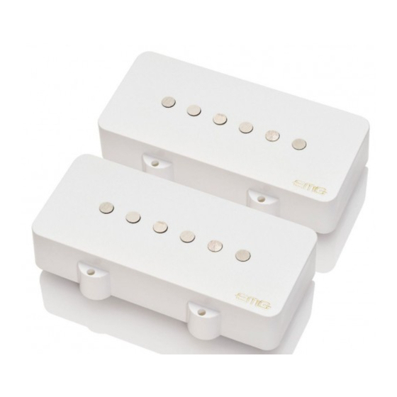
The JMASTER* Set is an active pickup option for Jazzmaster** style guitars. The contents of this set allow for a basic control scheme consisting
of master volume, master tone, and a three-position toggle switch (not included).
many Jazzmaster style guitars will NOT be compatible with the EMG JMASTER Pickups, and should be removed or disconnected when installing
the JMASTER Set.
If you'd like to add a robust active EQ section to your instrument, please consider the EMG JMASTER SYSTEM which is available
as a pre-loaded pickguard. The standalone JMASTER Set is intended for more basic setups and/or instruments which lack sufficient cavity space
for upper horn controls. Please verify that your instrument's pickguard can accommodate the JMASTER Pickups before installation.
Included with each set:
1 VOLUME CONTROL (25K)
1 TONE CONTROL (25K)
.235
.390
.310
(10)
STEREO OUTPUT
BATTERY
BUSS
*JMASTER is a registered trademark of EMG, Inc.
**JAZZMASTER is a trademark of Fender Musical Instruments Corporation
Warranty
All EMG Pickups and accessories are warranted for a period of two years. This warranty does not cover failure due to improper installation, abuse or damage. If
upon examination the pickup is determined to be defective, a replacement will be made. Warranty replacement products are covered by this same warranty. This
warranty covers only those pickups and accessories sold by authorized EMG Dealers. This warranty is not transferable.
© 2023 Copyright EMG INC. All Rights Reserved.
(41.3)
MODEL:
JMASTER
Gold
Alnico V
3.15
0.50
0.80
-120
3.16
350
715
27
ADJUSTMENT SCREWS (x12)
(6)
(8)
2 PICKUP IN/ OUT
BATTERY BUSS (B245)
JACK
1.625
The unique upper horn controls (i.e. rhythm circuit) found on
PICKUP CABLE 15" (38cm)
PICKUP CABLE 11" (28cm)
2 CONNECT CABLES 5.5" (14cm)
OUTPUT CABLE 6" (15cm)
BATTERY CABLE 7" (18cm)
- 9V +
3.625
(92.1)
1.610
(40.9)
.40 TYP
R .187 TYP
(4.75)
1.800
(45.7)
.843
(21.4)
Advertisement
Table of Contents

Related Manuals for EMG JMASTER SET


Summary of Contents for EMG JMASTER SET
- Page 1 Warranty All EMG Pickups and accessories are warranted for a period of two years. This warranty does not cover failure due to improper installation, abuse or damage. If upon examination the pickup is determined to be defective, a replacement will be made. Warranty replacement products are covered by this same warranty. This warranty covers only those pickups and accessories sold by authorized EMG Dealers.
- Page 2 Direct mounting your pickups will require placing hard foam beneath each pickup. Many instruments will already have foam underneath the stock pickups, but you may also cut a piece from the packaging foam that comes with your EMG Pickups. Installation (Two Pickup Guitars with Selection Switch): Guitars with two pickups and a selection switch will use the EMG B245 Pickup Buss as shown in Diagram #2.
- Page 3 2 Pickups / Toggle Select Switch / 2 Volumes (No Tone Control) Note: This configuration utilizes a second 25K volume control that is not included in the JMASTER Set. Additional solderless controls are available at emgpickups.com Refer to Diagram #4 1) Install the pickups and route the pickup cables to the control cavity.
- Page 4 2 Pickups / Toggle Select Switch / Master Volume / Active Accessory (SPC, EXG, VLPF, etc.) Note: This configuration utilizes an active accessory that is not included in the JMASTER Set. Additional solderless controls are available at emgpickups.com Refer to Diagram #7 4) Plug a connect cable from the Pickup Buss (Position 3) to the Input of the Active 1) Install the pickups and and route the pickup cables to the control cavity.
Need help?
Do you have a question about the JMASTER SET and is the answer not in the manual?
Questions and answers