Table of Contents
Advertisement
Quick Links
Advertisement
Table of Contents

Related Manuals for TEXA NAVIGATOR TXB Zero


Summary of Contents for TEXA NAVIGATOR TXB Zero
- Page 1 NAVIGATOR TXB Zero Rev.01...
- Page 2 ENGLISH..............5...
-
Page 4: Table Of Contents
4.4 Operator Safety....................10 4.5 Tool Safety......................11 4.6 Disclaimer.......................12 5 OPERATION OF THE RADIO DEVICES...........14 6 ENVIRONMENTAL INFORMATION............15 7 NORMATIVE INFORMATION..............16 8 NAVIGATOR TXB Zero ................19 9 DESCRIPTION...................20 10 TECHNICAL FEATURES.................21 11 POWER SUPPLY..................23 12 POWER ON/OFF ..................24 12.1 Power on.......................24 12.2 Boot down.....................24... -
Page 6: Revision Of The Manual
NAVIGATOR TXB Z TECHNICAL MANUAL 1 REVISION OF THE MANUAL This document is the technical manual for the product:TXB Zero Document Review Number:01 Date of Issue:13/01/2023 Read this manual before using the product. Read the documents carefully whenever the General Risk symbol is shown. -
Page 7: Introduction
TEXA S.p.A. tool has been used based on the information within this manual. Any additions to this manual, useful in describing the new versions of the program and new functions associated to it, may be sent to you through our TEXA technical bulletin service. -
Page 8: Legend Of The Symbols Used
3 LEGEND OF THE SYMBOLS USED Some of the symbols indicated below may not be used in the manual. Toxic material hazard Floor level obstacle warning Explosive material hazard Laser beam hazard Electric shock hazard Low temperature danger - freezing Electromagnetic field hazard General Risk Flammable material hazard... - Page 9 This is not a safety symbol. It indicates important information.
-
Page 10: Safety Rules
The personnel in charge of using the diagnostic tools are required to follow the general safety rules and to use the NAVIGATOR TXB Zero device for its intended use only and to carry out the maintenance as described in this manual. -
Page 11: Operator Safety
• The operator must be completely clear-headed and sober when using the device; taking drugs or alcohol before or when operating the tool is strictly forbidden. • The operator must follow all the instructions provided in the technical documents. • The operator is required to wear adequate personal protective equipment (PPE) throughout the use of the tool. -
Page 12: Tool Safety
Safety Measures: • Wear adequate personal protective equipment during all the operating phases. • Do not handle or touch the tool or any accessories (e.g. cables) with wet hands. The current used during the operating phases generates electromagnetic fields (EMF) near the tool. Even though of low intensity, these fields may interfere with medical prostheses, such as pacemakers. -
Page 13: Disclaimer
Safety measures: • Do not wet the tool with water or other liquids. • If not otherwise specified, use the device on vehicles with a 12/24 V DC power supply and the chassis connected to the negative pole. • The connection for the tool's power supply should always take place with the battery system of the vehicle being tested. - Page 14 BIKE environment: • On-road use: • For safety reasons never drive the vehicle when the tool is connected to it. • Test bench use (dyno bench): • It is the responsibility of the operator to install the device and inform the driver about the correct use of the product.
-
Page 15: Operation Of The Radio Devices
5 OPERATION OF THE RADIO DEVICES Wireless connection with Bluetooth® technology The wireless connection with Bluetooth technology is a technology that supplies a standard and reliable method to exchange information between different devices, using radio waves. Products such as cellular phones, portable devices, computers, printers, cameras, pocket PCs etc. -
Page 16: Environmental Information
6 ENVIRONMENTAL INFORMATION Do not dispose of this product with other undifferentiated solid waste. For information regarding the disposal of this product please see the pamphlet supplied. -
Page 17: Normative Information
7 NORMATIVE INFORMATION Simplified EU Declaration of Conformity The manufacturer, TEXA S.p.A., declares that the radio equipment type NAVIGATOR TXB Zero is compliant with the following directives: • RED 2014/53/UE The complete text of the EU declaration of conformity is available at the following Internet address http://www.texa.it/download. -
Page 20: Navigator Txb Zero
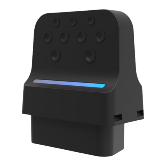
8 NAVIGATOR TXB Zero NAVIGATOR TXB Zero is a VCI (Vehicle Communication Interface) that can communicate with a large variety of vehicles. Thanks to the Bluetooth technology that this tool is equipped with, you can either work moving freely around the vehicle or work comfortably sitting in the vehicle. -
Page 21: Description
9 DESCRIPTION 1. LED 2. OBD connector... -
Page 22: Technical Features
10 TECHNICAL FEATURES Model: NAVIGATOR TXB Zero Manufacturer: TEXA S.p.A. Processor: ARM Cortex M4 (STM32F439ZIY6) • SDRAM: 8 MB Memory: • Flash NAND: 4 GB Vehicle Battery: 12Vdc and 24Vdc system management External power supply: 12 / 24 Vdc Wireless connection: Bluetooth Classic (2.1) - Page 23 Radio systems: ETSI EN 300 328 EN 62638-1 Safety: EN 62311 Data plate:...
-
Page 24: Power Supply
11 POWER SUPPLY The VCI is designed and manufactured to be powered directly from the battery in the vehicle being tested. Power is taken from the battery in the vehicle being tested via: • connection to the vehicle's diagnostic socket. The use of different power sources other than the ones indicated in this manual can damage the VCI. -
Page 25: Power On/Off
12 POWER ON/OFF In all the power source connection and disconnection operations, please refer to the safety indications in the POWER SUPPLY and DIAGNOSIS chapters in order to reduce the risk of electric shock. 12.1 Power on The VCI turns on automatically once it is connected to the vehicle's diagnostic socket. The green LED stays solid on if the VCI is properly powered. -
Page 26: Communication
13 COMMUNICATION The VCI communicates with the control units in the vehicle being tested via connection to the diagnostic socket. The VCI communicates with the display unit where the diagnostic software is installed via: • Bluetooth The Bluetooth communication is only possible with display units with Bluetooth 2.1 or higher. - Page 27 To configure the communication properly you must use the serial number indicated on the data plate on the VCI. When turning on the VCI, it automatically recognises the communication mode through which it is connected to the display unit. For further information, see the software operating manual.
-
Page 28: Diagnosis
14 DIAGNOSIS The protocols supported by the VCI allow it to perform various types of diagnoses. The type of diagnosis that can be carried out depends on the vehicle being tested and its compliance with specific protocols for communication with the control units. Where possible, the selection of the type of diagnosis is carried out through specific functions in the diagnostic software. -
Page 29: Standard Diagnosis
This mode of use is called REC (Recording) and allows checking the vehicle's behaviour during its normal use. For further information see the DYNAMIC TESTS chapter. 14.1 STANDARD diagnosis STANDARD diagnosis stand for a type of diagnosis based on the diagnostic protocols indicated in the TECHNICAL FEATURES chapter. -
Page 30: Dynamic Tests
14.2 Dynamic Tests The REC mode of the VCI allows checking the vehicle's behaviour during its normal use. The VCI can acquire and store data relating to the tests through the OBD connector of the vehicle to which it is connected. The data that can be stored includes the following: •... - Page 31 I.INSTALLATION 1. Turn off the vehicle (instrument panel off). 2. Locate the OBD connector. 3. Carefully remove any panels protecting the OBD connector. For further information, please refer to the documentation provided by the vehicle manufacturer. 4. Connect the additional diagnostic cable, if necessary, to the diagnostic connector on the VCI.
- Page 32 II.CONFIGURATION 9. Turn on the vehicle (instrument panel on). 10. Start the diagnostic software. 11. Connect the VCI to the display unit via Bluetooth or USB. (If previously configured, the wireless connection is automatic) 12. Select the vehicle on which you wish to operate. 13.
-
Page 33: Disconnection At The End Of A Diagnosis
III.DYNAMIC TESTS While carrying out the dynamic tests, simply drive as usual. You do not have to take the display unit with you. During the dynamic tests, the only vehicle occupants must be authorised repair technicians. The sampling of the parameters generally takes place every second. Any errors that may occur during the tests are stored within the memory of the VCI. - Page 34 The unexpected unfastening of any panels protecting the OBD connector may expose to the risk of hindrance to driving, and in particular to the activation of safety devices. Make sure any panels protecting the OBD connector that were previously removed and then reinstalled are secured in place, so that they do not fall off while driving.
-
Page 35: Firmware Update
15 FIRMWARE UPDATE The firmware in the VCI is updated through a specific software function and requires the connection to the display unit. Connection to the display unit is established via: • Bluetooth The available connection modes depend on the display unit used;... -
Page 36: Blink Codes
16 BLINK CODES The VCI uses LEDs to indicate its status both while connected to the vehicle and to the display unit. STATUS VCI not powered. GREEN VCI powered. Flashing VCI in communication with the vehicle's control unit. Flashing Error. -
Page 37: Maintenance
• only use original spare parts or spare parts approved by the manufacturer; • contact your retailer for extraordinary maintenance operations; For further help, contact your retailer or the technical assistance service. You can see the list of authorised retailers at the following address:https://www.texa.com/sales-network... -
Page 38: Legal Notices
18 LEGAL NOTICES TEXA S.p.A. Via 1 Maggio, 9 - 31050 Monastier di Treviso - ITALY Tax Code - Company Register of Treviso ID No. - VAT No.: 02413550266 Single-shareholder company subject to the direction and coordination activities of Opera Holding S.r.l.
Need help?
Do you have a question about the NAVIGATOR TXB Zero and is the answer not in the manual?
Questions and answers