Table of Contents
Advertisement
Quick Links
Advertisement
Table of Contents
Troubleshooting

Related Manuals for Supermicro SuperServer SSG-121E-NES24R


Summary of Contents for Supermicro SuperServer SSG-121E-NES24R
- Page 1 SuperServer ® SSG-121E-NES24R USER’S MANUAL Revision 1.0...
- Page 2 State of California, USA. The State of California, County of Santa Clara shall be the exclusive venue for the resolution of any such disputes. Supermicro's total liability for all claims will not exceed the price paid for the hardware product.
- Page 3 If you have any questions, please contact our support team at: support@supermicro.com This manual may be periodically updated without notice. Please check the Supermicro website for possible updates to the manual revision level. Secure Data Deletion A secure data deletion tool designed to fully erase all data from storage devices can be found on our website: https://www.supermicro.com/about/policies/disclaimer.cfm?url=/wdl/utility/...
-
Page 4: Table Of Contents
Preface Contents Chapter 1 Introduction 1.1 Overview ..........................9 1.2 System Features ........................10 Front View .........................10 Drive Carrier Indicators ....................10 Control Panel .........................12 Rear View ..........................13 Power Supply Indicator ....................13 1.3 System Architecture ......................14 1.4 Motherboard Layout ......................16 Quick Reference Table ......................17 Motherboard Block Diagram .....................19 Chapter 2 Server Installation 2.1 Overview ..........................20... - Page 5 Preface Chapter 3 Maintenance and Component Installation 3.1 Removing Power ........................29 3.2 Accessing the System ......................30 3.3 Processor and Heatsink Installation ...................31 The 4th Gen. Intel Xeon Scalable Processor ..............31 Overview of the CPU Socket ....................35 Overview of the Processor Carrier Assembly ..............36 3.
- Page 6 Preface 3.9 PCI Expansion Cards ......................68 3.10 Cable Routing Diagram .....................69 Chapter 4 Motherboard Connections 4.1 Power Connections ......................70 4.2 Headers and Connectors ....................71 4.3 Jumpers ..........................74 4.4 LED Indicators ........................75 Chapter 5 Software 5.1 Microsoft Windows OS Installation ..................76 5.2 Driver Installation ........................78 5.3 SuperDoctor 5 ........................79...
- Page 7 7.7 Where to Get Replacement Components ................98 7.8 Reporting an Issue ......................98 Technical Support Procedures ..................98 Returning Merchandise for Service ...................98 Vendor Support Filing System ..................99 7.9 Feedback ..........................99 7.10 Contacting Supermicro ....................100 Appendix A Standardized Warning Statements for AC Systems Appendix B System Specifications...
- Page 8 Super Micro Computer, Inc. 980 Rock Ave. San Jose, CA 95131 U.S.A. Tel: +1 (408) 503-8000 Fax: +1 (408) 503-8008 Email: marketing@supermicro.com (General Information) support@supermicro.com (Technical Support) Website: www.supermicro.com Europe Address: Super Micro Computer B.V. Het Sterrenbeeld 28, 5215 ML...
-
Page 9: Chapter 1 Introduction
1U; (WxHxD) 17.2" x 1.7" x 30.4" in. (437 x 43 x 772 mm) A Quick Reference Guide can be found on the product page of the Supermicro website. The following safety models associated with the SSG-121E-NES24R have been certified as... -
Page 10: System Features
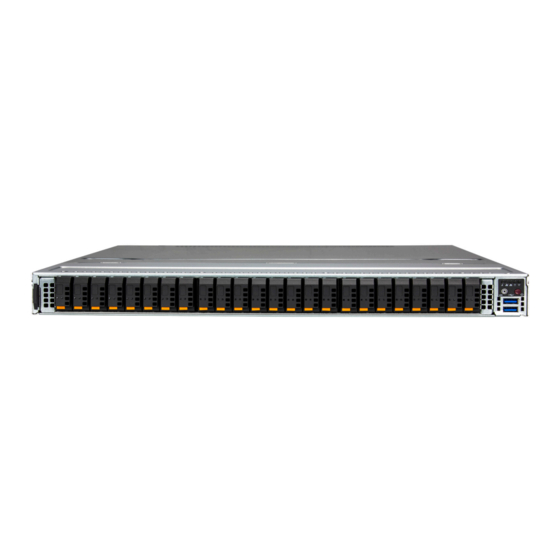
Chapter 1: Introduction 1.2 System Features The following views of the system display the main features. Front View Control Panel 10 11 12 13 14 15 16 17 18 19 20 21 22 23 Pull-out Tag USB Ports Figure 1-1. Front View System Features: Front Feature Description... - Page 11 Chapter 1: Introduction Drive Carrier LED Indicators Color Blinking Pattern Behavior for Device Blue Solid On Idle SAS/NVMe drive installed Activity Blue Blinking I/O activity Idle SATA drive installed Solid On Failure of drive with RSTe support Blinking at 1 Hz Rebuild drive with RSTe support Blinking with two blinks Hot spare for drive with RSTe support...
-
Page 12: Control Panel
Chapter 1: Introduction Control Panel Information LED NIC LED Power LED NIC LED Power Reset Figure 1-2. Control Panel Control Panel Features Feature Description The main power switch applies or removes primary power from the power supply to the server Power button but maintains standby power. -
Page 13: Rear View
Chapter 1: Introduction Rear View Ports PWS2 PWS1 IPMI Port Port Figure 1-3. System: Rear View System Features: Rear Feature Description Power Supplies Two redundant power supply modules, PWS1 on the right, PWS2 on the left IPMI Port Dedicated LAN port for IPMI; for indicator details, see BMC LAN LEDs USB Ports Two USB 3.0 ports... -
Page 14: System Architecture
Chapter 1: Introduction 1.3 System Architecture This section shows the locations of the system electronic components. Power Supply Modules M.2 Drives Motherboard X13DSF-A DIMM Slots Processors, Heatsinks System Fans System Fans Storage Backplane BPN-E1S5-126ES2N Figure 1-4. Main Component Locations... - Page 15 Chapter 1: Introduction System Features: Top Feature Description Power Supply Dual redundant modules DIMM Slots 32 DIMM DDR5 memory slots Processors Dual 4th Gen Intel Xeon scalable processors (up to 270W) with heatsinks M.2 Drives Two M.2 NVMe/SATA drives System Fans Eight 8-cm fans with optimal fan speed control Motherboard X13DSF-A...
-
Page 16: Motherboard Layout
Chapter 1: Introduction 1.4 Motherboard Layout Below is a layout of the X13DSF-A motherboard with jumper, connector and LED locations shown. See the table on the following page for descriptions. For detailed descriptions, pinout information and jumper settings, refer to Chapter 4 or the Motherboard Manual. -
Page 17: Quick Reference Table
MT1_1, MT2_1: M.2-H1 Mounting Holes; MT1_2, MT2_2 MT1_2, MT2_2: M.2-H2 Mounting Holes P1-AIOM (J139), Supermicro Advanced Input/Output Module (AIOM) PCIe 5.0 x16 Connectors for rear I/O P2-AIOM (J7) support (OCP 3.0 SFF compliant) P1_NVME0/1 - Six PCIe 5.0 x8 MCIO Connectors supported by CPU1... - Page 18 Chapter 1: Introduction Note: For details on how to configure Network Interface Card (NIC) settings, please refer to the Network Interface Card Configuration User's Guide posted on our website under the link: http://www.supermicro.com/support/manuals/.
-
Page 19: Motherboard Block Diagram
Chapter 1: Introduction Motherboard Block Diagram X13DSF-A REAR RJ45 RTL8211F JLAN1 Dedicated LAN Dedicated LAN U126 eMMC REAR USB CONN eMMC PE[13] JCOM1 COM CONN JUSB3 USB3.0/2.0 USB2.0 REAR USB3[0,1] [8,9] USB2[4,5] JVGA1 VGA CONN eSPI REAR AST2600A3 JTPM1 JUSB2 USB Header USB3[2,3] BMC Boot Flash... -
Page 20: Chapter 2 Server Installation
Chapter 2: Server Installation Chapter 2 Server Installation 2.1 Overview This chapter provides advice and instructions for mounting your system in a server rack. If your system is not already fully integrated with processors, system memory etc., refer to Chapter 3 for details on installing those specific components. -
Page 21: Rack Precautions
Chapter 2: Server Installation • This product is not suitable for use with visual display workplace devices according to §2 of the German Ordinance for Work with Visual Display Units. Rack Precautions • Ensure that the leveling jacks on the bottom of the rack are extended to the floor so that the full weight of the rack rests on them. -
Page 22: Airflow
Chapter 2: Server Installation Airflow Equipment should be mounted into a rack so that the amount of airflow required for safe operation is not compromised. Mechanical Loading Equipment should be mounted into a rack so that a hazardous condition does not arise due to uneven mechanical loading. -
Page 23: Installing The Rails
Chapter 2: Server Installation 2.4 Installing the Rails There are a variety of rack units on the market, which may require a slightly different assembly procedure. This rail set fits a rack between 26.8" and 36.4" deep. The following is a basic guideline for installing the system into a rack with the rack mounting hardware provided. -
Page 24: Releasing The Inner Rail
Chapter 2: Server Installation Releasing the Inner Rail Each inner rail has a locking latch. This latch prevents the server from coming completely out of the rack when when the chassis is pulled out for servicing. To mount the rail onto the chassis, first release the inner rail from the outer rails. 1. -
Page 25: Installing The Inner Rails On The Chassis
Chapter 2: Server Installation Installing the Inner Rails on the Chassis Installing the Inner Rails 1. Identify the left and right inner rails. They are labeled. 2. Place the inner rail firmly against the side of the chassis, aligning the hooks on the side of the chassis with the holes in the inner rail. -
Page 26: Installing The Outer Rails Onto The Rack
Chapter 2: Server Installation Installing the Outer Rails onto the Rack Each end of the assembled outer rail includes a bracket with hooks and square, spring-loaded pegs to fit into the square holes in your rack. Installing the Outer Rail 1. -
Page 27: Installing The Chassis Into A Rack
Chapter 2: Server Installation 2.5 Installing the Chassis into a Rack Once rails are attached to the chassis and the rack, you can install the server. Warning: Mounting the system into the rack requires at least two people to support the chassis during installation. -
Page 28: Removing The Chassis From The Rack
Chapter 2: Server Installation Removing the Chassis from the Rack Caution! It is dangerous for a single person to off-load the heavy chassis from the rack without assistance. Be sure to have sufficient assistance supporting the chassis when removing it from the rack. -
Page 29: Chapter 3 Maintenance And Component Installation
Chapter 3: Maintenance and Component Installation Chapter 3 Maintenance and Component Installation This chapter provides instructions on installing and replacing main system components. To prevent compatibility issues, only use components that match the specifications and/or part numbers given. Installation or replacement of most components require that power first be removed from the system. -
Page 30: Accessing The System
Chapter 3: Maintenance and Component Installation 3.2 Accessing the System The chassis features a removable top cover for access to the internal components. Removing the Chassis Cover 1. Remove power from the system as described in Section 3.1. 2. Remove the screws securing the cover to the chassis. 3. -
Page 31: Processor And Heatsink Installation
Thermal grease is pre-applied on a new heatsink. No additional thermal grease is needed. • Refer to the Supermicro website for updates on processor and memory support. • All graphics in this manual are for illustrations only. Your components may look different. - Page 32 Chapter 3: Maintenance and Component Installation 1. The 4th Gen. Intel Xeon Scalable Processor Processor Top View SP XCC SP MCC CPU Key CPU Key Pin 1 Pin 1 = Cutout = Pin 1 = CPU Key = Cutout = Pin 1 = CPU Key...
- Page 33 Chapter 3: Maintenance and Component Installation 2. The Processor Carrier Carrier E1B Carrier E1A Pin 1 Pin 1 Carrier Top View Carrier Bottom View = Cutout = Pin 1 = CPU Key = Cutout = Pin 1 = CPU Key...
- Page 34 Chapter 3: Maintenance and Component Installation 3. Heatsink 1U Heatsink Note: Exercise extreme care when handling the heatsink. Pay attention to the edges of heatsink fins, which can be sharp! To avoid damaging the heatsink, please do not apply excessive force on the fins.
-
Page 35: Overview Of The Cpu Socket
Chapter 3: Maintenance and Component Installation Overview of the CPU Socket The CPU socket is protected by a plastic protective cover. Plastic Protective Cover CPU Socket... -
Page 36: Overview Of The Processor Carrier Assembly
Chapter 3: Maintenance and Component Installation Overview of the Processor Carrier Assembly The processor carrier assembly contains a 4th Gen. Intel Xeon Scalable processor and a processor carrier. Carefully follow the instructions given in the installation section to place a processor into the carrier to create a processor carrier assembly. -
Page 37: Overview Of The Processor Heatsink Module (Phm) With Sp Xcc And Carrier E1A
Chapter 3: Maintenance and Component Installation Overview of the Processor Heatsink Module (PHM) with SP XCC and Carrier E1A The Processor Heatsink Module (PHM) contains a heatsink, a processor carrier, and a 4th Gen. Intel Xeon Scalable processor. 1. Heatsink 1U Heatsink (Bottom View) 2. -
Page 38: Overview Of The Processor Heatsink Module (Phm) With Sp Mcc And Carrier E1B
Chapter 3: Maintenance and Component Installation Overview of the Processor Heatsink Module (PHM) with SP MCC and Carrier E1B The Processor Heatsink Module (PHM) contains a heatsink, a processor carrier, and a 4th Gen. Intel Xeon Scalable processor. 1. Heatsink 1U Heatsink (Bottom View) 2. -
Page 39: Creating The Processor Carrier Assembly
Chapter 3: Maintenance and Component Installation Creating the Processor Carrier Assembly The processor carrier assembly contains a 4th Gen. Intel Xeon Scalable processor and a processor carrier. To create the processor carrier assembly, please follow the steps below: Note: Before installation, be sure to follow the instructions given on pages 1 and 2 of this chapter to properly prepare for installation. - Page 40 Chapter 3: Maintenance and Component Installation 2. First, turn over the processor carrier and locate Pin 1 on the CPU and Pin 1 on the carrier. Then, turn the processor over with component side (including the gold contacts) facing up and locate CPU keys on the processor. Finally, locate the CPU keys and four latches on the carrier as shown below.
- Page 41 Chapter 3: Maintenance and Component Installation 3. Locate the lever on the CPU socket and press it down as shown below. Lever Lever Carrier E1A Carrier E1B 4. Using Pin 1 as a guide, carefully align the CPU keys (marked A and B) on the processor against the CPU keys on the carrier (marked a and b) as shown below.
- Page 42 Chapter 3: Maintenance and Component Installation 6. After the processor is placed inside the carrier, examine the four sides of the processor, making sure that the processor is properly seated on the carrier. Processor Carrier Assembly Processor Carrier Assembly (Top View) (Component Side) SP XCC SP MCC...
-
Page 43: Creating The Phm
Chapter 3: Maintenance and Component Installation Creating the PHM After creating the processor carrier assembly, please follow the instructions below to mount the processor carrier into the heatsink to form the PHM. Note: If this is a new heatsink, the thermal grease has been pre-applied on the underside. Otherwise, apply the proper amount of thermal grease. -
Page 44: Creating The Phm (1U Heatsink)
Chapter 3: Maintenance and Component Installation Creating the PHM (1U Heatsink) Processor Carrier Assembly Processor Carrier Assembly (Component Side) (Component Side) (SP XCC, Carrier E1A) (SP MCC, Carrier E1B) Pin 1 Pin 1 Heatsink (Bottom Side) Heatsink (Bottom Side) PHM (Top View) PHM (1U Heatsink) -
Page 45: Preparing The Cpu Socket For Installation
Chapter 3: Maintenance and Component Installation Preparing the CPU Socket for Installation This motherboard comes with a plastic protective cover installed on the CPU socket. Remove it from the socket by following the instructions below. 1. Press the tabs inward. 2. -
Page 46: Preparing To Install The Phm Into The Cpu Socket
Chapter 3: Maintenance and Component Installation Preparing to Install the PHM into the CPU Socket After assembling the Processor Heatsink Module (PHM), you are ready to install it into the CPU socket. To ensure the proper installation, please follow the procedures below. 1. - Page 47 Chapter 3: Maintenance and Component Installation 2. Locate four peek nuts (marked A, B, C, D) and four rotating wires (marked 1, 2, 3, 4) on the heatsink as shown below. 1U Heatsink (Top Side) A, B, C, D: Peek Nut Rotating Wire 1, 2, 3, 4: Rotating Wire a, b, c, d: Threaded Fastener...
- Page 48 Chapter 3: Maintenance and Component Installation 3. Check the rotating wires (marked 1, 2, 3, 4) to make sure that they are at unlatched positions as shown below before installing the PHM into the CPU socket. Unlatched State Top View Side View Rotating Wire 1 Peek Nut...
-
Page 49: Installing The Phm Into The Cpu Socket
Chapter 3: Maintenance and Component Installation Installing the PHM into the CPU Socket 1. Align peek nut (marked A) on the heatsink against threaded fastener (marked a) on the CPU socket. Then align peek nuts (marked B, C, D) on the heatsink against threaded fasteners (marked b, c, d) on the CPU socket, making sure that all peek nuts on the heatsink are properly aligned with the correspondent threaded fasteners on the CPU socket. - Page 50 Chapter 3: Maintenance and Component Installation 3. Press all four rotating wires outwards and make sure that the heatsink is securely latched onto the CPU socket. Latched State 1U Heatsink...
- Page 51 Chapter 3: Maintenance and Component Installation 4. With a T30 screwdriver, tighten all peek nuts in the sequence of A, B, C, and D with even pressure. To avoid damaging the processor or socket, do not use excessive force when tightening the peek nuts. (For best durability, 8in-lbf torque is recommended.) 5.
-
Page 52: Removing The Phm From The Cpu Socket
Chapter 3: Maintenance and Component Installation Removing the PHM from the CPU Socket Before removing the PHM from the motherboard, be sure to shut down the system and unplug the power cables from the power supply. Then follow the steps below. 1. -
Page 53: Removing The Processor Carrier Assembly From The Phm
Chapter 3: Maintenance and Component Installation 3. Gently pull the PHM upwards to remove it from the CPU socket. 1U Heatsink Removing the Processor Carrier Assembly from the PHM To remove the processor carrier assembly from the PHM, please follow the steps below. 1. - Page 54 Chapter 3: Maintenance and Component Installation 2. When all plastic clips are detached from the heatsink, remove the processor carrier assembly from the heatsink. SP XCC SP MCC 1U Heatsink (Bottom View)
-
Page 55: Removing The Processor From The Processor Carrier Assembly
Chapter 3: Maintenance and Component Installation Removing the Processor from the Processor Carrier Assembly Once you have removed the processor carrier assembly from the PHM, you are ready to remove the processor from the processor carrier by following the steps below. 1. -
Page 56: Memory
Chapter 3: Maintenance and Component Installation 3.4 Memory Memory Support The X13DSF-A has 16 DIMM slots for up to 12TB of 256Gb 3DS RDIMM/RDIMM DDR5 ECC memory and 512Gb Intel Optane PMem 300 Series with speeds of 4800MT/s. Intel Optane PMem is supported by the 4th Gen Intel Xeon scalable Platinum, Gold and selected Silver processors only. -
Page 57: Memory Population For The X13Dp Motherboards (With 32 Dimm Slots)
2 CPUs & 24 DIMMs DIMME1/P1-DIMME2/P1-DIMMF1/P1-DIMMF2/P1-DIMMG1/P1-DIMMG2/P1-DIMMH1/P1-DIMMH2 CPU2: P2-DIMMA1/P2-DIMMB1/P2-DIMMC1/P2-DIMMD1/P2-DIMME1/P2-DIMMF1/P2-DIMMG1/P2-DIMMH1 CPU1: P1-DIMMA1/P1-DIMMA2/P1-DIMMB1/P1-DIMMB2/P1-DIMMC1/P1-DIMMC2/P1-DIMMD1/P1-DIMMD2/P1- DIMME1/P1-DIMME2/P1-DIMMF1/P1-DIMMF2/P1-DIMMG1/P1-DIMMG2/P1-DIMMH1/P1-DIMMH2 2 CPUs & 32 DIMMs CPU2: P2-DIMMA1/P2-DIMMA2/P2-DIMMB1/P2-DIMMB2/P2-DIMMC1/P2-DIMMC2/P2-DIMMD1/P2-DIMMD2/P2- DIMME1/P2-DIMME2/P2-DIMMF1/P2-DIMMF2/P2-DIMMG1/P2-DIMMG2/P2-DIMMH1/P2-DIMMH2 Note: This memory configuration is recommended by Supermicro for optimal memory performance. Please use this configuration to maximize your memory performance. -
Page 58: Pmem 300 Series Population Table For X13Dp Motherboards (With 32 Dimm Slots)
Chapter 3: Maintenance and Component Installation PMem 300 Series Population Table for X13DP Motherboards (with 32 DIMM Slots) Note: The Intel Optane Persistent Memory (PMem) 300 Series are supported by the 4th Gen. Intel Xeon Scalable (84xx/64xx/54xx Series) Processors. PMem 300 Series Population Table for X13DP Motherboards (with 32 DIMMs Installed) DDR5+ Mode DIMMH1... -
Page 59: Memory Population Guidelines
Balance memory. Using unbalanced memory topology, such as populating two DIMMs in one channel while populating one DIMM in another channel, reduces performance. It is not recommended for Supermicro systems. • In dual-CPU configurations, memory must be installed in the slots associated with the installed CPUs. -
Page 60: Installing Memory
Chapter 3: Maintenance and Component Installation Installing Memory ESD Precautions Electrostatic Discharge (ESD) can damage electronic com ponents including memory modules. To avoid damaging DIMM modules, it is important to handle them carefully. The following measures are generally sufficient. • Use a grounded wrist strap designed to prevent static discharge. -
Page 61: Motherboard Battery
Chapter 3: Maintenance and Component Installation 3.5 Motherboard Battery The motherboard uses non-volatile memory to retain system information when system power is removed. This memory is powered by a lithium battery residing on the motherboard. Replacing the Battery Begin by removing power from the system. -
Page 62: Storage Drives
The drives are mounted in toolless drive carriers that simplify their removal from the chassis. These carriers also help promote proper airflow. Note: Enterprise level hard disk drives are recommended for use in Supermicro chassis and servers. For information on recommended HDDs, visit the Supermicro website product pages at www.supermicro.com/products. - Page 63 Chapter 3: Maintenance and Component Installation Removing a Hot-Swap Drive Carrier from the Chassis 1. Press the release button on the drive carrier, which will extend the drive carrier handle. 2. Use the drive carrier handle to pull the drive out of the chassis. Figure 3-5.
-
Page 64: System Cooling
Chapter 3: Maintenance and Component Installation 2. Insert a drive into the carrier with the connector end toward the rear of the carrier. Align the drive in the carrier so that the screw holes line up. 3. Secure the drive to the carrier with the two screws from the carrier. These screws are included in the chassis accessory box. -
Page 65: Installing The Air Shrouds
Chapter 3: Maintenance and Component Installation Installing the Air Shrouds Air shrouds concentrate airflow to maximize fan efficiency. They do not require screws to install. Installing the Standard Air Shrouds • Position the air shrouds as illustrated in the figure below, sliding the front over the edge of the fan tray. -
Page 66: Power Supply
• Solid Amber: When illuminated, indicates that the power supply is plugged in, and is in an abnormal state. The system might need service. Please contact Supermicro technical support. Changing the Power Supply Module: 1. Unplug the AC cord from the module to be replaced. - Page 67 Chapter 3: Maintenance and Component Installation Release Tab Figure 3-9. Replacing the Power Supply...
-
Page 68: Pci Expansion Cards
Chapter 3: Maintenance and Component Installation 3.9 PCI Expansion Cards The system accepts up to four PCIe expansion cards. Figure 3-10. Expansion Slots Expansion Card Chassis Slots Item Description PCIe 5.0 x16 slot PCIe 5.0 x16 slot AIOM1 AIOM2 Installing an Expansion Card 1. -
Page 69: Cable Routing Diagram
Chapter 3: Maintenance and Component Installation 3.10 Cable Routing Diagram Use this section to route or reroute cables. Proper routing is important to maintain airflow through the system. Cable part numbers and descriptions are available at the Online Cable Matrix. MCIO Cables Backplane Power Cables Front Panel Control Cables... -
Page 70: Chapter 4 Motherboard Connections
Chapter 4: Motherboard Connections Chapter 4 Motherboard Connections This section describes the jumpers, connections and LEDs on the motherboard and provides pinout definitions. Some connections might not be used in this system. A motherboard layout indicating component locations may be found in Chapter 1. -
Page 71: Headers And Connectors
The JTPM1 header is used to connect a Trusted Platform Module (TPM)/Port 80, which is available from Supermicro (optional). A TPM/Port 80 connector is a security device that supports encryption and authentication in hard drives. It allows the motherboard to deny access if the TPM, which is associated with the hard drive, is not installed in the system. - Page 72 Note: For detailed instructions on how to configure Network Interface Card (NIC) settings, please refer to the Network Interface Card Configuration User's Guide posted on the web page under the link: http://www.supermicro.com/support/manuals/. Chassis Intrusion A Chassis Intrusion header is located at JL1 on the motherboard. Attach the appropriate cable from the chassis to inform you when the chassis is opened.
- Page 73 Chapter 4: Motherboard Connections SATA 3.0 Connector A SATA 3.0 connector, located at JS1, supports four SATA 3.0 connections (SATA 0~3) on the motherboard. The SATA 3.0 connector is supported by the Intel C741 chipset. Connecting a proper SATA cable to JS1 to use SATA 3.0 connections. MCIO NVMe Connectors Twelve MCIO NVMe connectors, located at P1_NVME0/1 - P1_NVME10/11 (supported by CPU1) and P2_NVME0/1 - P2_NVME10/11 (supported by CPU2), provide 24 NVMe PCIe...
-
Page 74: Jumpers
Chapter 4: Motherboard Connections 4.3 Jumpers Explanation of Jumpers To modify the operation of the motherboard, jumpers are used to choose between optional settings. Jumpers create shorts between two pins to change the function associated with it. Pin 1 is identified with a square solder pad on the printed circuit board. See the motherboard layout page for jumper locations. -
Page 75: Led Indicators
Chapter 4: Motherboard Connections 4.4 LED Indicators BMC Heartbeat LED A BMC Heartbeat LED is located at LEDBMC on the motherboard. When LEDBMC is blinking green, the BMC is functioning normally. Refer to the layout below for the location of LEDBMC. BMC Heartbeat LED Indicator LED Color Definition... -
Page 76: Chapter 5 Software
If you will be using RAID, you must configure RAID settings before installing the Windows OS and the RAID driver. Refer to the RAID Configuration User Guides posted on our website at www.supermicro.com/support/manuals. Installing the OS 1. Create a method to access the MS Windows installation ISO file. That might be a USB flash or media drive, perhaps using an external USB/SATA flash or media drive, or the BMC KVM console. - Page 77 Chapter 5: Software 3. During Windows Setup, continue to the dialog where you select the drives on which to install Windows. If the disk you want to use is not listed, click on “Load driver” link at the bottom left corner. Figure 5-2.
-
Page 78: Driver Installation
The Supermicro website contains drivers and utilities for your system at https://www. supermicro.com/wdl/driver. Some of these must be installed, such as the chipset driver. After accessing the website, go into the CDR_Images (in the parent directory of the above link) and locate the ISO file for your motherboard. Download this file to a USB flash or media drive. -
Page 79: Superdoctor ® 5
5.3 SuperDoctor ® The Supermicro SuperDoctor 5 is a program that functions in a command-line or web-based interface for Windows and Linux operating systems. The program monitors such system health information as CPU temperature, system voltages, system power consumption, fan speed, and provides alerts via email or Simple Network Management Protocol (SNMP). -
Page 80: Bmc
There are several BIOS settings that are related to BMC. For general documentation and information on BMC, visit our website at: www.supermicro.com/en/solutions/management-software/bmc-resources BMC ADMIN User Password For security, each system is assigned a unique default BMC password for the ADMIN user. -
Page 81: Chapter 6 Optional Components
Storage Control Card and Cable(s) TPM security module Intel VROC RAID Key 6.1 Storage Control Card and Cable(s) Supermicro offers storage controller cards for various data protection and drive RAID levels. Please refer to the product page for the latest cards and add-on options. -
Page 82: Tpm Security Module
It enables the motherboard to deny access if the TPM associated with the hard drive is not installed in the system. Details and installation procedures are at: http://www.supermicro.com/manuals/other/TPM.pdf. • AOM-TPM-9670H •... -
Page 83: Intel Virtual Raid On Cpu (Vroc)
Chapter 6: Optional Components 6.3 Intel Virtual RAID on CPU (VROC) Intel Virtual RAID on CPU (Intel VROC) is an enterprise RAID solution for NVMe SSDs ® directly attached to Intel Xeon Scalable processors. Intel Volume Management Device (VMD) is an integrated controller inside the CPU PCIe root complex. •... -
Page 84: Additional Information
Chapter 6: Optional Components Additional Information Additional information is available on the product page for the Supermicro add-on card and the linked manuals. www.supermicro.com/products/accessories/addon/AOC-VROCxxxMOD.cfm Hardware Key The Intel VROC hardware key is a license key that detects the Intel VROC SKU and activates the function accordingly. -
Page 85: Configuring Nvme Raid Manually
Chapter 6: Optional Components Configuring NVMe RAID Manually RAID for NVMe SSDs is enabled by default when Intel VROC Raid Key is populated. It may be managed manually through the UEFI BIOS. 1. Reboot the server and press [DEL] key to access the BIOS options. 2. - Page 86 Chapter 6: Optional Components Figure 6-3. BIOS, Manual Mode (Example—your server may look different.) 3. Select the desired PStack# to Enable or Disable the corresponding Intel VMD controller Figure 6-4. BIOS, Enabling VMD for Pstack0...
- Page 87 Chapter 6: Optional Components 4. Select the desired PCIe slot to Enable or Disable Intel VMD functionality according to the current hardware configuration being used. Hot Plug Capability can also be Enabled or Disabled. Figure 6-5. BIOS, Enabling VMD Functionality per Slot 5.
- Page 88 Chapter 6: Optional Components Figure 6-7. BIOS, Enabling CPU2 Example 6. Press [F4] to save the configuration and reboot the system and press [DEL] to enter BIOS. Note: Disabling the VMD controller without first deleting the associated existing RAID volume can lead to unexpected behavior. This action is strongly not recommended. Note: The effects of physically changing or swapping a CPU on the VMD controller enablement has not yet been thoroughly tested or documented.
- Page 89 Chapter 6: Optional Components 10. If cross-controller RAID is required, select Enable RAID spanned over VMD Controller. Figure 6-8. Created Volume without Figure 6-9. Created Volume with enabling RAID spanned over VMD enabling RAID spanned over VMD controller controller 11. Select specific disks for RAID with an [X]. •...
-
Page 90: Status Indications
Chapter 6: Optional Components Status Indications An LED indicator on the drive carrier shows the RAID status of the drive. Drive Carrier Status LED Indicator Status State (red) Normal function Locating 4 Hz blink Fault Solid on Rebuilding 1 Hz Blink IBPI SFF 8489 Defined Status LED States Hot Swap Drives Intel VMD enables hot-plug and hot-unplug for NVMe SSDs, whether from Intel or other... -
Page 91: Chapter 7 Troubleshooting And Support
Chapter 7 Troubleshooting and Support 7.1 Information Resources Website A great deal of information is available on the Supermicro website, www.supermicro.com. Figure 7-1. Supermicro Website • Specifications for servers and other hardware are available by clicking the Products option. •... -
Page 92: Baseboard Management Controller (Bmc)
Security Center for recent security notices Supermicro Phone and Addresses 7.2 Baseboard Management Controller (BMC) The system supports the Baseboard Management Controller (BMC). BMC is used to provide remote access, monitoring and management. There are several BIOS settings that are related to BMC. -
Page 93: Troubleshooting Procedures
Chapter 7: Troubleshooting and Support 7.3 Troubleshooting Procedures Use the following procedures to troubleshoot your system. If you have followed all of the procedures below and still need assistance, refer to the Technical Support Procedures Returning Merchandise for Service sections in this chapter. Power down the system before changing any non hot-swap hardware components. -
Page 94: No Video
Chapter 7: Troubleshooting and Support 9. Check that the power supplies’ input voltage operate at 100-120v or 180-240v. 10. Turn the power switch on and off to test the system No Video 1. If the power is on but you have no video, remove all the add-on cards and cables. 2. - Page 95 2. Memory support: Make sure that the memory modules are supported by testing the modules using memtest86 or a similar utility. Note: Refer to the product page on our website at http://www.supermicro.com for memory and CPU support and updates. 3. HDD support: Make sure that all hard disk drives (HDDs) work properly. Replace the bad HDDs with good ones.
-
Page 96: Crash Dump Using Bmc
Chapter 7: Troubleshooting and Support 7.4 Crash Dump Using BMC In the event of a processor internal error (IERR) that crashes your system, you may want to provide information to support staff. You can download a crash dump of status information using BMC. -
Page 97: Cmos Clear
Chapter 7: Troubleshooting and Support 7.5 CMOS Clear JBT1 is used to clear CMOS, which will also clear any passwords. Instead of pins, this jumper consists of contact pads to prevent accidentally clearing the contents of CMOS. To Clear CMOS 1. -
Page 98: Where To Get Replacement Components
7.7 Where to Get Replacement Components If you need replacement parts for your system, to ensure the highest level of professional service and technical support, purchase exclusively from our Supermicro Authorized Distributors/System Integrators/Resellers. A list can be found at: http://www.supermicro.com. -
Page 99: Vendor Support Filing System
Chapter 7: Troubleshooting and Support Whenever possible, repack the chassis in the original Supermicro carton, using the original packaging material. If these are no longer available, be sure to pack the chassis securely, using packaging material to surround the chassis so that it does not shift within the carton and become damaged during shipping. -
Page 100: Contacting Supermicro
Chapter 7: Troubleshooting and Support 7.10 Contacting Supermicro Headquarters Address: Super Micro Computer, Inc. 980 Rock Ave. San Jose, CA 95131 U.S.A. Tel: +1 (408) 503-8000 Fax: +1 (408) 503-8008 Email: marketing@supermicro.com (General Information) support@supermicro.com (Technical Support) Website: www.supermicro.com Europe Address: Super Micro Computer B.V. -
Page 101: Appendix A Standardized Warning Statements For Ac Systems
Should you have questions or experience difficulty, contact Supermicro's Technical Support department for assistance. Only certified technicians should attempt to install or configure components. Read this appendix in its entirety before installing or configuring components in the Supermicro chassis. T h e s e... - Page 102 Appendix A: Warning Statements Warnung WICHTIGE SICHERHEITSHINWEISE Dieses Warnsymbol bedeutet Gefahr. Sie befinden sich in einer Situation, die zu Verletzungen führen kann. Machen Sie sich vor der Arbeit mit Geräten mit den Gefahren elektrischer Schaltungen und den üblichen Verfahren zur Vorbeugung vor Unfällen vertraut. Suchen Sie mit der am Ende jeder Warnung angegebenen Anweisungsnummer nach der jeweiligen Übersetzung in den übersetzten Sicherheitshinweisen, die zusammen mit diesem Gerät ausgeliefert wurden.
- Page 103 Appendix A: Warning Statements . ٌ ا ك ً ف حالة و ٌ يك أى تتسبب ف اصابة جسذ ة ٌ هذا الزهز ع ٌ خطز !تحذ ز قبل أى تعول عىل أي هعذات،يك عىل علن بالوخاطز ال ا ٌجوة عي الذوائز ٍ...
- Page 104 Appendix A: Warning Statements Warnung Vor dem Anschließen des Systems an die Stromquelle die Installationsanweisungen lesen. ¡Advertencia! Lea las instrucciones de instalación antes de conectar el sistema a la red de alimentación. Attention Avant de brancher le système sur la source d'alimentation, consulter les directives d'installation. .יש...
- Page 105 Appendix A: Warning Statements Warnung Dieses Produkt ist darauf angewiesen, dass im Gebäude ein Kurzschluss- bzw. Überstromschutz installiert ist. Stellen Sie sicher, dass der Nennwert der Schutzvorrichtung nicht mehr als: 250 V, 20 A beträgt. ¡Advertencia! Este equipo utiliza el sistema de protección contra cortocircuitos (o sobrecorrientes) del edificio.
- Page 106 Appendix A: Warning Statements Power Disconnection Warning Warning! The system must be disconnected from all sources of power and the power cord removed from the power supply module(s) before accessing the chassis interior to install or remove system components. 電源切断の警告 システムコンポーネントの取り付けまたは取り外しのために、...
- Page 107 Appendix A: Warning Statements אזהרה מפני ניתוק חשמלי !אזהרה יש לנתק את המערכת מכל מקורות החשמל ויש להסיר את כבל החשמלי מהספק .לפני גישה לחלק הפנימי של המארז לצורך התקנת או הסרת רכיבים يجب فصم اننظاو من جميع مصادر انطاقت وإ ز انت سهك انكهرباء من وحدة امداد انطاقت...
- Page 108 Appendix A: Warning Statements Equipment Installation Warning! Only trained and qualified personnel should be allowed to install, replace, or service this equipment. 機器の設置 トレーニングを受け認定された人だけがこの装置の設置、 交換、 またはサービスを許可されていま す。 警告 只有经过培训且具有资格的人员才能进行此设备的安装、更换和维修。 警告 只有經過受訓且具資格人員才可安裝、更換與維修此設備。 Warnung Das Installieren, Ersetzen oder Bedienen dieser Ausrüstung sollte nur geschultem, qualifiziertem Personal gestattet werden.
- Page 109 Appendix A: Warning Statements Restricted Area Warning! This unit is intended for installation in restricted access areas. A restricted access area can be accessed only through the use of a special tool, lock and key, or other means of security. (This warning does not apply to workstations). アクセス制限区域...
- Page 110 Appendix A: Warning Statements אזור עם גישה מוגבלת !אזהרה יש להתקין את היחידה באזורים שיש בהם הגבלת גישה. הגישה ניתנת בעזרת (.'כלי אבטחה בלבד (מפתח, מנעול וכד . تخصيص هذه انىحذة نترك ب ُ ها ف مناطق محظورة تم ، م َ كن انىصىل إن منطقت محظورة فقط من خالل استخذاو أداة خاصت أو...
- Page 111 Appendix A: Warning Statements Warnung Bei Einsetzen einer falschen Batterie besteht Explosionsgefahr. Ersetzen Sie die Batterie nur durch den gleichen oder vom Hersteller empfohlenen Batterietyp. Entsorgen Sie die benutzten Batterien nach den Anweisungen des Herstellers. Attention Danger d'explosion si la pile n'est pas remplacée correctement. Ne la remplacer que par une pile de type semblable ou équivalent, recommandée par le fabricant.
- Page 112 Appendix A: Warning Statements Redundant Power Supplies Warning! This unit might have more than one power supply connection. All connec- tions must be removed to de-energize the unit. 冗長電源装置 このユニッ トは複数の電源装置が接続されている場合があります。 ユニッ トの電源を切るためには、 すべての接続を取り外さなければなりません。 警告 此部件连接的电源可能不止一个,必须将所有电源断开才能停止给该部件供电。 警告 此裝置連接的電源可能不只一個,必須切斷所有電源才能停止對該裝置的供電。 Warnung Dieses Gerät kann mehr als eine Stromzufuhr haben. Um sicherzustellen, dass der Einheit kein trom zugeführt wird, müssen alle Verbindungen entfernt werden.
- Page 113 Appendix A: Warning Statements אם קיים יותר מספק אחד !אזהרה ליחדה יש יותר מחיבור אחד של ספק. יש להסיר את כל החיבורים על מנת לרוקן .את היחידה . قد يكون لهذا الجهاز عدة اتصاالت بوحدات امداد الطاقة يجب إ ز الة كافة االتصاالت لعسل الوحدة عن الكهرباء 경고! 이...
- Page 114 Appendix A: Warning Statements Warnung Wenn das System in Betrieb ist, treten auf der Rückwandplatine gefährliche Spannungen oder Energien auf. Vorsicht bei der Wartung. ¡Advertencia! Cuando el sistema está en funcionamiento, el voltaje del plano trasero es peligroso. Tenga cuidado cuando lo revise. Attention Lorsque le système est en fonctionnement, des tensions électriques circulent sur le fond de panier.
- Page 115 Appendix A: Warning Statements Comply with Local and National Electrical Codes Warning! Installation of the equipment must comply with local and national electrical codes. 地方および国の電気規格に準拠 機器の取り付けはその地方および国の電気規格に準拠する必要があります。 警告 设备安装必须符合本地与本国电气法规。 警告 設備安裝必須符合本地與本國電氣法規。 Warnung Die Installation der Geräte muss den Sicherheitsstandards entsprechen. ¡Advertencia! La instalacion del equipo debe cumplir con las normas de electricidad locales y nacionales.
- Page 116 Appendix A: Warning Statements Product Disposal Warning! Ultimate disposal of this product should be handled according to all national laws and regulations. 製品の廃棄 この製品を廃棄処分する場合、 国の関係する全ての法律 ・ 条例に従い処理する必要があります。 警告 本产品的废弃处理应根据所有国家的法律和规章进行。 警告 本產品的廢棄處理應根據所有國家的法律和規章進行。 Warnung Die Entsorgung dieses Produkts sollte gemäß allen Bestimmungen und Gesetzen des Landes erfolgen.
- Page 117 Appendix A: Warning Statements Hot Swap Fan Warning Warning! Hazardous moving parts. Keep away from moving fan blades. The fans might still be turning when you remove the fan assembly from the chassis. Keep fingers, screwdrivers, and other objects away from the openings in the fan assembly's housing. ファン...
- Page 118 Electrical Appliance and Material Safety Law prohibits the use of UL or CSA -certified cables (that have UL/CSA shown on the cord) for any other electrical devices than products designated by Supermicro only. 電源コードとACアダプター...
- Page 119 Verbindungskabeln, Stromkabeln und/oder Adapater, die Ihre örtlichen Sicherheitsstandards einhalten. Der Gebrauch von anderen Kabeln und Adapter können Fehlfunktionen oder Feuer verursachen. Die Richtlinien untersagen das Nutzen von UL oder CAS zertifizierten Kabeln (mit UL/CSA gekennzeichnet), an Geräten oder Produkten die nicht mit Supermicro gekennzeichnet sind. ¡Advertencia! Cuando instale el producto, utilice la conexión provista o designada o procure cables, Cables...
- Page 120 .قيرح وأ لطع يف ببستي دق ىرخأ تالوحمو تالباك يأ مادختسا .ميلسلا سباقلاو لصوملا مجح لبق نم ةدمتعملا تالباكلا مادختسا تادعملاو ةيئابرهكلا ةزهجألل ةمالسلا نوناق رظحيUL وأCSA ( ةمالع لمحت يتلاوUL/CSA) لبق نم ةددحملاو ةينعملا تاجتنملا ريغ ىرخأ تادعم يأ عمSupermicro. 전원 케이블 및 AC 어댑터...
-
Page 121: Appendix B System Specifications
Appendix B: System Specifications Appendix B System Specifications Processors 4th Gen Intel Xeon scalable processor with 4 UPI (16 GT/s max) and a total of 160 Gen5 PCIe lanes in P (LGA-4677) socket Chipset Intel PCH C621A BIOS 128Mb AMI BIOS SPI Flash EEPROM Memory 32 DIMM slots;... - Page 122 Appendix B: System Specifications Operating Environment Operating Temperature: 0º to 50º C (32º to 122º F) Non-operating Temperature: -10º to 60º C (14º to 140º F) Operating Relative Humidity: 20% to 90% (non-condensing) Non-operating Relative Humidity: 5% to 95% (non-condensing) Certified Safety Models Compliant with UL or CSA: 826-R8X12, 826-8 Regulatory Compliance...
Need help?
Do you have a question about the SuperServer SSG-121E-NES24R and is the answer not in the manual?
Questions and answers