Table of Contents
Advertisement
Quick Links
Advertisement
Table of Contents

Related Manuals for Supermicro SuperStorage SSG-136R-4MU32JBF


Summary of Contents for Supermicro SuperStorage SSG-136R-4MU32JBF
- Page 1 SuperStorage SSG-136R-4MU32JBF USER’S MANUAL Revision 1.0...
- Page 2 State of California, USA. The State of California, County of Santa Clara shall be the exclusive venue for the resolution of any such disputes. Supermicro's total liability for all claims will not exceed the price paid for the hardware product.
- Page 3 If you have any questions, please contact our support team at: support@supermicro.com This manual may be periodically updated without notice. Please check the Supermicro website for possible updates to the manual revision level. Secure Data Deletion A secure data deletion tool designed to fully erase all data from storage devices can be found on our website: https://www.supermicro.com/about/policies/disclaimer.cfm?url=/wdl/utility/...
-
Page 4: Table Of Contents
Preface Contents Contacting Supermicro ......................6 Chapter 1 Introduction 1.1 Overview ..........................7 1.2 Unpacking the System ......................7 1.3 System Features ........................8 1.4 System Chassis Features ....................9 Control Panels ........................9 Front Features ........................10 Rear Features ........................11 Sled Features ........................12 1.5 Controller Board Layout .....................13 Quick Reference Table ......................13... - Page 5 SuperStorage SSG-136R-4MU32JBF User's Manual Installing the Chassis onto the Rack ................23 2.4 Powering On the System ....................24 2.5 Assigning Drives to Host Servers ..................24 Chapter 3 Maintenance and Component Installation 3.1 Removing Power ........................25 3.2 Accessing the System ......................25 3.3 Chassis Components ......................27 Drives ..........................27...
-
Page 6: Contacting Supermicro
SuperStorage SSG-136R-4MU32JBF User's Manual Contacting Supermicro Headquarters Address: Super Micro Computer, Inc. 980 Rock Ave. San Jose, CA 95131 U.S.A. Tel: +1 (408) 503-8000 Fax: +1 (408) 503-8008 Email: marketing@supermicro.com (General Information) Sales-USA@supermicro.com (Sales Inquiries) Government_Sales-USA@supermicro.com (Gov. Sales Inquiries) support@supermicro.com (Technical Support) RMA@supermicro.com (RMA Support) -
Page 7: Chapter 1 Introduction
UL or CSA: 136U2JBOF-10, 136JOBF. 1.2 Unpacking the System Inspect the box the SuperStorage SSG-136R-4MU32JBF was shipped in and note if it was damaged in any way. If any equipment appears damaged, please file a damage claim with the carrier who delivered it. -
Page 8: System Features
SuperStorage SSG-136R-4MU32JBF User's Manual 1.3 System Features The following table provides you with an overview of the main features of the SSG-136R-4MU32JBF. Refer to Appendix B for additional specifications. System Features Controller Board BPN-NVME4-136PL-J Chassis CSE-136TS-R1K04JP-U2 Expansion Slots Two PCIe 3.0 x16 slots Four External PCIe 3.0 x16 ports... -
Page 9: System Chassis Features
Chapter 1: Introduction 1.4 System Chassis Features Control Panels The switches and LEDs located on the control panels are described below. Two control panels are located on the front of the chassis. Figure 1-1. Control Panel View Control Panel Features Item Feature Description... -
Page 10: Front Features
SuperStorage SSG-136R-4MU32JBF User's Manual Information LED Status Description Solid red Power supply failure. Blinking red (1Hz) Fan failure. Check for an inoperative fan. BMC service is powering on. Do not power Blinking red (4Hz) on hosts connected to the system until this is finished. -
Page 11: Rear Features
Chapter 1: Introduction Rear Features The illustration below shows the features included on the rear of the chassis. PSU1 PSU2 Figure 1-4. Chassis Rear View Rear Chassis Features Item Feature Description 1000W power supply module with LED. Two modules for power Power Supply redundancy (PSU1 on left, PSU2 on right). -
Page 12: Sled Features
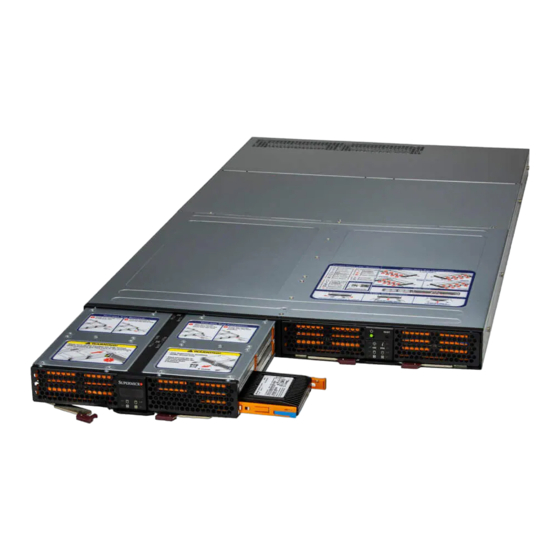
SuperStorage SSG-136R-4MU32JBF User's Manual Sled Features The chassis contains two sleds that each hold 16 NVMe SSDs. The sleds extend from the front of the chassis to provide access to hot-swap drive carriers located on each side of the sled. Refer to Chapter 3 for instructions on accessing the drive carriers. -
Page 13: Controller Board Layout
Chapter 1: Introduction 1.5 Controller Board Layout Below is a layout of the BPN-NVME4-136PL-J. See the following table for jumper descriptions. Figure 1-6. Controller Board Layout Quick Reference Table Jumper Description Default Setting JPB1 BMC Enable Pins 1-2 (Enabled) Chassis Intrusion Open Note: BMC must always be enabled. -
Page 14: Ports
SuperStorage SSG-136R-4MU32JBF User's Manual 1.6 Ports Figure 1-7. Rear I/O Panel Description IPMI LAN Ports x16 PCIe External Port UID Button IPMI LAN Ports Two 1G IPMI LAN ports (LAN1/2) are located on the I/O back panel. If both ports are plugged in, LAN1 is the active port and LAN2 is redundant. -
Page 15: Chapter 2 System Installation
Chapter 2: System Installation Chapter 2 System Installation 2.1 Overview This chapter provides advice and instructions for mounting your system in a server rack. If your system is not already fully integrated with drives, fans etc., refer to Chapter 3 for details on installing those specific components. -
Page 16: System Precautions
SuperStorage SSG-136R-4MU32JBF User's Manual • In single rack installations, stabilizers should be attached to the rack. In multiple rack in- stallations, the racks should be coupled together. • Always verify that the rack is stable before extending a server or other component from the rack. -
Page 17: Circuit Overloading
Chapter 2: System Installation Circuit Overloading Consideration should be given to the connection of the equipment to the power supply circuitry and the effect that any possible overloading of circuits might have on overcurrent protection and power supply wiring. Appropriate consideration of equipment nameplate ratings should be used when addressing this concern. -
Page 18: Installing The System Into A Rack
SuperStorage SSG-136R-4MU32JBF User's Manual 2.3 Installing the System into a Rack This section provides information on installing the 136TS-R1K04JP-U2 chassis into a rack unit with the rails provided. Due to the variety of rack units on the market, the assembly procedure might differ slightly. -
Page 19: Releasing The Inner Rails
Chapter 2: System Installation Releasing the Inner Rails Releasing the Inner Rails from the Outer Rails 1. Pull the inner rail out of the outer rail until it is fully extended as illustrated below. 2. Press the locking tab down to release the inner rail. 3. -
Page 20: Installing The Inner Rails On The Chassis
SuperStorage SSG-136R-4MU32JBF User's Manual Installing The Inner Rails on the Chassis Installing the Inner Rails 1. Place the inner rail firmly against the side of the chassis, aligning the hooks on the side of the chassis with the holes in the inner rail. -
Page 21: Installing The Outer Rails On The Rack
Chapter 2: System Installation Installing the Outer Rails on the Rack Installing the Outer Rails 1. If your rack has round mounting holes, adjust the fittings on the outer rails. Press the latch at the end of the rail to change from square fittings to round fittings. Figure 2-4. - Page 22 SuperStorage SSG-136R-4MU32JBF User's Manual 2. Push the middle rail back into the outer rail. An audible click indicates that the rail is fully inserted. Figure 2-5. Adjusting the Middle Rail 3. Insert the pegs on the rear of the outer rail into the rear rack holes. An audible click indicates that the rail is locked into place.
-
Page 23: Installing The Chassis Onto The Rack
Chapter 2: System Installation Installing the Chassis onto the Rack Installing the Chassis onto the Rack 1. Fully extend the outer rails as illustrated in Figure 2-7. 2. Align the inner rails of the chassis with the outer rails on the rack. 3. -
Page 24: Powering On The System
Note, if no NVMe SSD drives are installed in the JBOF, the ‘L Drive Tray’ and the ‘R Drive Tray’ will remain blank until SSD drives have been inserted. If other sensor readings are not reporting green, please consult with Supermicro tech support for assistance. -
Page 25: Chapter 3 Maintenance And Component Installation
SuperStorage SSG-136R-4MU32JBF User's Manual Chapter 3 Maintenance and Component Installation This chapter provides instructions on installing and replacing main system components. To prevent compatibility issues, only use components that match the specifications and/or part numbers given. Installation or replacement of most components require that power first be removed from the system. - Page 26 Chapter 3: Maintenance and Component Installation Side Screws Figure 3-1. Removing the Chassis Cover...
-
Page 27: Chassis Components
Sled #2 Figure 3-2. Extending the Sled Notes: 1. Do not leave a sled extended from the chassis for longer than two minutes. 2. Use Supermicro qualified NVMe SSDs only. For information on recommended SSDs, visit the Supermicro website at http://www.supermicro.com/products/nfo/storage.cfm. - Page 28 Chapter 3: Maintenance and Component Installation Mounting a Drive in a Drive Carrier 1. Release and swing open the locking latches on the side of the drive carrier. 2. Insert a drive into the carrier with the PCB side facing down and the connector end toward the rear of the carrier.
- Page 29 SuperStorage SSG-136R-4MU32JBF User's Manual Removing a Drive 1. Push the release tab on the drive carrier that you want to remove. 2. Use the release tab to retract the drive carrier from its bay, then fully remove the drive carrier and its drive.
-
Page 30: System Cooling
Chapter 3: Maintenance and Component Installation System Cooling Eight 4-cm hot-swap fans provide the cooling for the system. It is very important that the chassis top cover is properly installed and forms a seal in order for the cooling air to circulate properly through the chassis and cool the components. -
Page 31: Power Supply
If either of the two power supply modules fail, the other will take the full load and allow the system to continue operation without interruption. The Power Fail LED illuminates until the failed module has been replaced. Replacements can be ordered directly from Supermicro (see contact information in the Preface). The power supply modules have a hot-swap capability, so you can replace the failed module without powering down the system. -
Page 32: Pcie Cables
Chapter 3: Maintenance and Component Installation PCIe Cables PCIe cabling is required to connect the SSG-136R-4MU32JBF to the server node's host interface card(s). The chassis has four x16 external PCIe ports, which can be split to eight x8 ports to support up to eight hosts. Connect the PCIe cable from the server node's host interface card (P/N AOC-SLG4-4X4T) to the first set of ports. - Page 33 SuperStorage SSG-136R-4MU32JBF User's Manual AOC-SLG4-4X4T Server #1 with Host Interface Card External PCIe Cables Server #3 Server #4 Server #2 with Host Interface Card AOC-SLG4-4X4T Figure 3-10. Four Servers (Dual x8 PCIe Cables)
- Page 34 Chapter 3: Maintenance and Component Installation Server #1 Server #2 Server #3 Server #4 AOC-SLG4-4X4T AOC-SLG4-4X4T AOC-SLG4-4X4T AOC-SLG4-4X4T External PCIe Cables AOC-SLG4-4X4T AOC-SLG4-4X4T AOC-SLG4-4X4T AOC-SLG4-4X4T Server #5 Server #6 Server #7 Server #8 Figure 3-11. Eight Servers (Single x8 PCIe Cables)
-
Page 35: Pcie Expansion Cards
SuperStorage SSG-136R-4MU32JBF User's Manual PCIe Expansion Cards The SSG-136R-4MU32JBF can accommodate up to two full-height PCIe expansion cards in the rear slots. These are only used for NVMeoF configurations, 6-host configurations, and 12-host configurations. Installing an Add-on Card Begin by removing power from the system as described in Section 3.1 and removing the cover as described in Section 3.2. -
Page 36: Appendix A Standardized Warning Statements For Ac Systems
Supermicro's Technical Support department for assistance. Only certified technicians should attempt to install or configure components. Read this appendix in its entirety before installing or configuring components in the Supermicro chassis. These warnings may also be found on our website at http://www.supermicro.com/about/... - Page 37 Appendix B: Standardized Warning Statements Warnung WICHTIGE SICHERHEITSHINWEISE Dieses Warnsymbol bedeutet Gefahr. Sie befinden sich in einer Situation, die zu Verletzungen führen kann. Machen Sie sich vor der Arbeit mit Geräten mit den Gefahren elektrischer Schaltungen und den üblichen Verfahren zur Vorbeugung vor Unfällen vertraut. Suchen Sie mit der am Ende jeder Warnung angegebenen Anweisungsnummer nach der jeweiligen Übersetzung in den übersetzten Sicherheitshinweisen, die zusammen mit diesem Gerät ausgeliefert wurden.
- Page 38 SuperStorage SSG-136R-4MU32JBF User's Manual . ٌ ا ك ً ف حالة و ٌ يك أى تتسبب ف اصابة جسذ ة ٌ هذا الزهز ع ٌ خطز !تحذ ز قبل أى تعول عىل أي هعذات،يك عىل علن بالوخاطز ال ا ٌجوة عي الذوائز...
- Page 39 Appendix B: Standardized Warning Statements Warnung Vor dem Anschließen des Systems an die Stromquelle die Installationsanweisungen lesen. ¡Advertencia! Lea las instrucciones de instalación antes de conectar el sistema a la red de alimentación. Attention Avant de brancher le système sur la source d'alimentation, consulter les directives d'installation. .יש...
- Page 40 SuperStorage SSG-136R-4MU32JBF User's Manual Warnung Dieses Produkt ist darauf angewiesen, dass im Gebäude ein Kurzschluss- bzw. Überstromschutz installiert ist. Stellen Sie sicher, dass der Nennwert der Schutzvorrichtung nicht mehr als: 250 V, 20 A beträgt. ¡Advertencia! Este equipo utiliza el sistema de protección contra cortocircuitos (o sobrecorrientes) del edificio.
- Page 41 Appendix B: Standardized Warning Statements Power Disconnection Warning Warning! The system must be disconnected from all sources of power and the power cord removed from the power supply module(s) before accessing the chassis interior to install or remove system components. 電源切断の警告...
- Page 42 SuperStorage SSG-136R-4MU32JBF User's Manual אזהרה מפני ניתוק חשמלי !אזהרה יש לנתק את המערכת מכל מקורות החשמל ויש להסיר את כבל החשמלי מהספק .לפני גישה לחלק הפנימי של המארז לצורך התקנת או הסרת רכיבים يجب فصم اننظاو من جميع مصادر انطاقت وإ ز انت سهك انكهرباء من وحدة امداد...
- Page 43 Appendix B: Standardized Warning Statements Attention Il est vivement recommandé de confier l'installation, le remplacement et la maintenance de ces équipements à des personnels qualifiés et expérimentés. !אזהרה .צוות מוסמך בלבד רשאי להתקין, להחליף את הציוד או לתת שירות עבור הציוד واملدربيه...
- Page 44 SuperStorage SSG-136R-4MU32JBF User's Manual Warnung Diese Einheit ist zur Installation in Bereichen mit beschränktem Zutritt vorgesehen. Der Zutritt zu derartigen Bereichen ist nur mit einem Spezialwerkzeug, Schloss und Schlüssel oder einer sonstigen Sicherheitsvorkehrung möglich. ¡Advertencia! Esta unidad ha sido diseñada para instalación en áreas de acceso restringido. Sólo puede obtenerse acceso a una de estas áreas mediante la utilización de una herramienta especial,...
- Page 45 Appendix B: Standardized Warning Statements Battery Handling Warning! There is the danger of explosion if the battery is replaced incorrectly. Replace the battery only with the same or equivalent type recommended by the manufacturer. Dispose of used batteries according to the manufacturer's instructions 電池の取り扱い...
- Page 46 SuperStorage SSG-136R-4MU32JBF User's Manual هناك خطر من انفجار يف حالة اسحبذال البطارية بطريقة غري صحيحة فعليل اسحبذال البطارية فقط بنفس النىع أو ما يعادلها مام أوصث به الرشمة املصنعة جخلص من البطاريات املسحعملة وفقا لحعليامت الرشمة الصانعة 경고! 배터리가 올바르게 교체되지 않으면 폭발의 위험이 있습니다. 기존 배터리와 동일하거나 제...
- Page 47 Appendix B: Standardized Warning Statements ¡Advertencia! Puede que esta unidad tenga más de una conexión para fuentes de alimentación. Para cortar por completo el suministro de energía, deben desconectarse todas las conexiones. Attention Cette unité peut avoir plus d'une connexion d'alimentation. Pour supprimer toute tension et tout courant électrique de l'unité, toutes les connexions d'alimentation doivent être débranchées.
- Page 48 SuperStorage SSG-136R-4MU32JBF User's Manual Backplane Voltage Warning! Hazardous voltage or energy is present on the backplane when the system is operating. Use caution when servicing. バックプレーンの電圧 システムの稼働中は危険な電圧または電力が、 バックプレーン上にかかっています。 修理する際には注意く ださい。 警告 当系统正在进行时,背板上有很危险的电压或能量,进行维修时务必小心。 警告 當系統正在進行時,背板上有危險的電壓或能量,進行維修時務必小心。 Warnung Wenn das System in Betrieb ist, treten auf der Rückwandplatine gefährliche Spannungen oder Energien auf.
- Page 49 Appendix B: Standardized Warning Statements هناك خطز مه التيار الكهزبايئ أوالطاقة املىجىدة عىل اللىحة عندما يكىن النظام يعمل كه حذ ر ا عند خدمة هذا الجهاس 경고! 시스템이 동작 중일 때 후면판 (Backplane)에는 위험한 전압이나 에너지가 발생 합니다. 서비스 작업 시 주의하십시오. Waarschuwing Een gevaarlijke spanning of energie is aanwezig op de backplane wanneer het systeem in gebruik is.
- Page 50 SuperStorage SSG-136R-4MU32JBF User's Manual תיאום חוקי החשמל הארצי !אזהרה .התקנת הציוד חייבת להיות תואמת לחוקי החשמל המקומיים והארציים تركيب املعدات الكهربائية يجب أن ميتثل للقىاويه املحلية والىطىية املتعلقة بالكهرباء 경고! 현 지역 및 국가의 전기 규정에 따라 장비를 설치해야 합니다.
- Page 51 Appendix B: Standardized Warning Statements Attention La mise au rebut ou le recyclage de ce produit sont généralement soumis à des lois et/ou directives de respect de l'environnement. Renseignez-vous auprès de l'organisme compétent. סילוק המוצר !אזהרה .סילוק סופי של מוצר זה חייב להיות בהתאם להנחיות וחוקי המדינה التخلص...
- Page 52 SuperStorage SSG-136R-4MU32JBF User's Manual Warnung Gefährlich Bewegende Teile. Von den bewegenden Lüfterblätter fern halten. Die Lüfter drehen sich u. U. noch, wenn die Lüfterbaugruppe aus dem Chassis genommen wird. Halten Sie Finger, Schraubendreher und andere Gegenstände von den Öffnungen des Lüftergehäuses entfernt.
- Page 53 Verbindungskabeln, Stromkabeln und/oder Adapater, die Ihre örtlichen Sicherheitsstandards einhalten. Der Gebrauch von anderen Kabeln und Adapter können Fehlfunktionen oder Feuer verursachen. Die Richtlinien untersagen das Nutzen von UL oder CAS zertifizierten Kabeln (mit UL/CSA gekennzeichnet), an Geräten oder Produkten die nicht mit Supermicro gekennzeichnet sind.
- Page 54 .قيرح وأ لطع يف ببستي دق ىرخأ تالوحمو تالباك يأ مادختسا .ميلسلا سباقلاو لصوملا مجح لبق نم ةدمتعملا تالباكلا مادختسا تادعملاو ةيئابرهكلا ةزهجألل ةمالسلا نوناق رظحيUL وأCSA ( ةمالع لمحت يتلاوUL/CSA) لبق نم ةددحملاو ةينعملا تاجتنملا ريغ ىرخأ تادعم يأ عمSupermicro.
- Page 55 사항을 준수하여 제공되거나 지정된 연결 혹은 구매 케이블, 전원 케이블 및 AC 어댑터를 사용하십시오. 다른 케이블이나 어댑터를 사용하면 오작동이나 화재가 발생할 수 있습니다. 전기 용품 안전법은 UL 또는 CSA 인증 케이블 (코드에 UL / CSA가 표시된 케이블)을 Supermicro 가 지정한 제품 이외의 전기 장치에 사용하는 것을 금지합니다. Stroomkabel en AC-Adapter...
-
Page 56: Appendix B System Specifications
SuperStorage SSG-136R-4MU32JBF User's Manual Appendix B System Specifications Drive Bays Thirty-two 2.5" NVMe SSDs in hot-swap drive carriers PCI Expansion Slots Two PCIe 3.0 x16 slots Four external PCIe 3.0 x16 ports Controller Board BPN-NVME4-136PL-J Chassis 136TS-R1K04JP-U2; 1U Rackmount, (WxHxD) 17.26 x 1.71 x 31.95 in. (438.4 x 43.6 x 811.7 mm) - Page 57 Appendix B: System Specifications Applied Directives, Standards EMC/EMI: 2014/30/EU (EMC Directive) FCC Part 15 Subpart B ICES-003 VCCI-CISPR 32 AS/NZS CISPR 32 EN/BS EN55024 EN/BS EN55032 EN/BS 61000-3-2 EN/BS 61000-3-3 EN/BS 61000-4-2 EN/BS 61000-4-3 EN/BS 61000-4-4 EN/BS 61000-4-5 EN/BS 61000-4-6 EN/BS 61000-4-8 EN/BS 61000-4-11 Green Environment:...
- Page 58 SuperStorage SSG-136R-4MU32JBF User's Manual Appendix C Drive Assignment C.1 Overview After installing the SSG-136R-4MU32JBF system, you must assign drives to hosts. This appendix provides information about drive mappings and procedures for reassigning drives to different hosts. Refer to the Web GUI or command line interface sections in this appendix for your preferred procedure.
-
Page 59: Appendix C Drive Assignment
Appendix C: Drive Assignment C.2 Drive Slots Endpoint Mapping Each physical drive is assigned an "endpoint" number that is different from the physical slot number. The following tables provide an overview of endpoint mapping for drive slots in a four-host and eight-host configuration. When assigning drives to hosts, start with the drives located closest to the front of the system and work your way back. -
Page 60: Endpoint Mapping: Eight Hosts
SuperStorage SSG-136R-4MU32JBF User's Manual Endpoint Mapping: Eight Hosts Drive Slots to Endpoint Mapping (Eight Hosts) Drive Slots to Endpoint Mapping (Eight Hosts) Bind 8Host- Bind 8Host-Left Drive# PhyPort Slot# Endpoint Zone Drive# PhyPort Slot# Endpoint Zone Order Right Order 136NB-L... - Page 61 Appendix C: Drive Assignment C.3 Assigning a Drive from the GUI Drive assignment from the Web GUI requires a computer with access to the network that contains your SSG-136R-4MU32JBF system. When assigning drives to hosts, start with the drives located closest to the front of the system and work your way back.
- Page 62 SuperStorage SSG-136R-4MU32JBF User's Manual C.4 Assigning a Drive from the CLI Drive assignment from the CLI requires Curl and Python with the json.tools module installed in a Linux environment. (Recommended versions: Curl 7.35.0 or later, Python 2.7.6 or later). When assigning drives to hosts, start with the drives located closest to the front of the system and work your way back.
- Page 63 Appendix C: Drive Assignment In the following example, endpoint 19 (drive 23) represents the only drive assigned to zone 1: "@odata.context": "/redfish/v1/$metadata#Zone.Zone", "@odata.id": "/redfish/v1/Fabrics/1/Zones/1", "@odata.type": "#Zone.Zone", "Description": "PCIe Zone 1", "Id": "1", "Links": { "Endpoints": [ "@odata.id": "/redfish/v1/Fabrics/1/Endpoints/1" "@odata.id": "/redfish/v1/Fabrics/1/Endpoints/19" "InvolvedSwitches": [ "@odata.id": "/redfish/v1/Fabrics/1/Switches/1"...
- Page 64 SuperStorage SSG-136R-4MU32JBF User's Manual Reassigning a Drive 1. To change drive assignment, you must first create a .txt file that includes your changes in JSON format. For example: "Endpoints": [ "@odata.id": "/redfish/v1/Fabrics/1/Endpoints/1" "@odata.id": "/redfish/v1/Fabrics/1/Endpoints/7" "@odata.id": "/redfish/v1/Fabrics/1/Endpoints/5" In the above example, endpoint 19 (drive 23) was removed from zone 1, and endpoints 7 and 5 (drives 29 and 31) were added to zone 1.
- Page 65 Appendix C: Drive Assignment C.5 Obtaining the System IP Address Drive reassignment requires the IP address of the SSG-136R-4MU32JBF system. Perform the following procedure to obtain the system IP address. If DHCP is detected, a dynamic IP address is assigned to the system. If DHCP is not detected, the default IP address is 192.168.1.99.
-
Page 66: Appendix D Firmware Updates
SuperStorage SSG-136R-4MU32JBF User's Manual Appendix D Firmware Updates D.1 Updating BMC Firmware Use IPMI to update the BMC firmware. 1. Log into the IPMI. The default Username and Password are ADMIN / ADMIN. 2. Under the Maintenance tab, select Firmware Management, then BMC then click the... - Page 67 Appendix D Firmware Updates 3. Click Select File to select the configuration file and click the Open button. 4. Check the file name and click the Update button. 5. Check the file version and click the Upload button.
-
Page 68: Updating Pcie Switch Configuration
SuperStorage SSG-136R-4MU32JBF User's Manual 6. Click OK to finish the update and reset the BMC. D.2 Updating PCIe Switch Configuration Use IPMI to update the configuration of the JBOF switches. 1. Log into the IPMI.The default Username and Password are ADMIN / ADMIN. - Page 69 Appendix D Firmware Updates 3. Click Select File to select configuration file and click the Open button 4. Check the file and click the Upload button. 5. Check the file version and click the Update button. 6. Click OK to finish then reset the system to complete the update.
-
Page 70: Updating Cpld Firmware
SuperStorage SSG-136R-4MU32JBF User's Manual D.3 Updating CPLD Firmware Use IPMI to update the CPLD firmware. 1. Log into the IPMI.The default Username and Password are ADMIN / ADMIN. 2. Under the Maintenance tab, select Firmware Management, then CPLD, and the Next button. - Page 71 Appendix D Firmware Updates 4. Check the file and click the Upload button. 5. Check the file version and click the Update button. 6. Click OK to finish, then reset the system to complete the update.
Need help?
Do you have a question about the SuperStorage SSG-136R-4MU32JBF and is the answer not in the manual?
Questions and answers