Advertisement
•
Refer to Service Manual RS6100004 for installation, operation, and troubleshooting information.
•
All safety information must be followed as provided in the Service Manual.
•
Refer to the appropriate Parts Catalog for part number information.
•
Models listed on page 3.
This manual is to be used by qualified, professionally trained HVAC technicians only. Goodman does
not assume any responsibility for property damage or personal injury due to improper service
procedures or services performed by an unqualified person.
TECHNICAL MANU
TECHNICAL MANU
TECHNICAL MANU AL
TECHNICAL MANU
TECHNICAL MANU
®
CKF 50 Hz
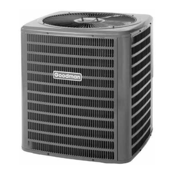
Condensing Units
Copyright ©
2007, 2010 - 2012 Goodman
Manufacturing Company, L.P.
Copyright © 2007 Goodman Manufacturing Company, L.P.
AL
AL
AL
AL
RT6111009r4
January 2012
Advertisement
Table of Contents

Summary of Contents for Goodman CKF Series
- Page 1 Refer to the appropriate Parts Catalog for part number information. • Models listed on page 3. This manual is to be used by qualified, professionally trained HVAC technicians only. Goodman does RT6111009r4 not assume any responsibility for property damage or personal injury due to improper service January 2012 procedures or services performed by an unqualified person.
-
Page 2: Product Identification
Failure to do so may cause property damage, personal injury or death. Installation and repair of this unit WARNING WARNING Goodman will not be responsible WARNING WARNING should be performed ONLY by for any injury or property damage individuals meeting the requirements, at a minimum, of arising from improper service or service procedures. - Page 3 WARNING that is not design certified by damage, personal injury, or death, Goodman for use with this unit. do not store combustible materials or use gasoline or Serious property damage, personal injury, reduced unit other flammable liquids or vapors in the vicinity of this performance and/or hazardous conditions may result appliance.
-
Page 4: Product Design
PRODUCT DESIGN CKF 50 Hz models are available in 2 through 6 ton sizes. They are designed for 220/240 to 380 volt single phase appli- cations. The condenser air is pulled through the condenser coil by a direct drive propeller fan. This condenser air is then dis- charged out of the top of the cabinet. - Page 5 PRODUCT DESIGN Dimensions Model Dimensions - W x D x H CKF24- 2* 26" [6 60] x 26" [66 0] x 29¾ [756] CKF36- 2* 26" [6 60] x 26" [66 0] x 29¾ [756] CKF36- 5* 26" [6 60] x 26" [66 0] x 29¾ [756] CKF48- 5* 29"...
-
Page 6: Condensing Unit Specifications
CONDENSING UNIT SPECIFICATIONS Cooli ng Capa ci ty, B TUH/kW 24600/7.2 34000/10.0 34000 /1 0.0 44000/12.9 55000/16 .1 64000/1 8.8 Compresso r 12.50 17.9 10.9 R.L . Amps 61.0 97.4 42.0 50.0 74.0 101.0 L.R. Amps 410/275 410/275 410/2 75 410/275 410/27 5 410/2 75... - Page 7 COOLING PERFORMANCE DATA CKF24-2*...
- Page 8 COOLING PERFORMANCE DATA CKF24-2*...
- Page 9 COOLING PERFORMANCE DATA CKF36-2*...
- Page 10 CKF36-2* COOLING PERFORMANCE DATA...
- Page 11 COOLING PERFORMANCE DATA CKF36-5*...
- Page 12 COOLING PERFORMANCE DATA CKF36-5*...
- Page 13 CKF48-5* COOLING PERFORMANCE DATA...
- Page 14 COOLING PERFORMANCE DATA CKF48-5*...
- Page 15 COOLING PERFORMANCE DATA CKF60-5*...
- Page 16 COOLING PERFORMANCE DATA CKF60-5*...
- Page 17 COOLING PERFORMANCE DATA CKF70-5*...
- Page 18 COOLING PERFORMANCE DATA CKF70-5*...
-
Page 19: Performance Data
PERFORMANCE DATA PERFORMANCE TEST All data based upon listed indoor dry bulb temperature. .00 inches external static pressure on coil of outdoor section. Indoor air cubic feet per minute (CFM) as listed in the Performance Data Sheets: If conditions vary from this, results will change as follows: As indoor dry bulb temperatures increase, a slight increase will occur in indoor air temperature drop (Delta T). -
Page 20: Wiring Diagrams
WIRING DIAGRAMS CKF[24-36]M/N/P HIGH VOLTAGE! DISCONNECT ALL POWER BEFORE SERVICING OR INSTALLING THIS UNIT. MULTIPLE POWER SOURCES MAY BE PRESENT. FAILURE TO DO SO MAY CAUSE PROPERTY DAMAGE, PERSONAL INJURY OR DEATH. Wiring is subject to change. Always refer to the wiring diagram on the unit for the most up-to-date wiring. - Page 21 WIRING DIAGRAMS CKF[48-70]M/N/P HIGH VOLTAGE! DISCONNECT ALL POWER BEFORE SERVICING OR INSTALLING THIS UNIT. MULTIPLE POWER SOURCES MAY BE PRESENT. FAILURE TO DO SO MAY CAUSE PROPERTY DAMAGE, PERSONAL INJURY OR DEATH. Wiring is subject to change. Always refer to the wiring diagram on the unit for the most up-to-date wiring.


Need help?
Do you have a question about the CKF Series and is the answer not in the manual?
Questions and answers