
Subscribe to Our Youtube Channel
Related Manuals for NI cRIO-9081


Summary of Contents for NI cRIO-9081
- Page 1 sales@artisantg.com artisantg.com (217) 352-9330 | Visit our website - Click HERE...
- Page 2 Getting Started 2022-07-15...
-
Page 3: Table Of Contents
Connecting the cRIO-9081 to a Network........12... -
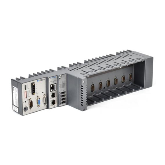
Page 4: Overview
Getting Started Overview This document describes how to begin using the NI cRIO-9081. 0 8 1 IO -9 Safety Guidelines Caution Observe all instructions and cautions in the user documentation. Using the model in a manner not specified can damage the model and compromise the built-in safety protection. - Page 5 Safety Guidelines for Hazardous Locations The cRIO-9081 is suitable for use in Class I, Division 2, Groups A, B, C, D, T4 hazardous locations; Class I, Zone 2, AEx nA IIC T4 Gc and Ex nA IIC T4 Gc hazardous locations;...
-
Page 6: Electromagnetic Compatibility Guidelines
Getting Started Caution Transient protection shall be provided that is set at a level not exceeding 140% of the peak rated voltage value of 85 V at the supply terminals to the equipment. Caution The system shall only be used in an area of not more than Pollution Degree 2, as defined in IEC/EN 60664-1. -
Page 7: Special Conditions For Marine Applications
EMC performance is attained. Preparing the Environment Ensure that the environment in which you are using the cRIO-9081 meets the following specifications. Operating temperature (IEC 60068-2-1, IEC 60068-2-2) 0 °C to 55 °C... -
Page 8: Verifying The Kit Contents
Verify that the following items are included in the cRIO-9081 kit. Installing Software on the Host Computer Before using the cRIO-9081, you must install the following application software and device drivers on the host computer in this order: 1. LabVIEW 2011 or later 2. -
Page 9: Removing C Series Modules
Verify that power is not connected to the I/O connector(s) on the C Series module before you remove a module from the cRIO-9081. If the system is in a nonhazardous location, the cRIO-9081 can be powered on when you remove modules. -
Page 10: Connecting The Crio-9081 To Power
Info Code emcground. Connecting the cRIO-9081 to Power The cRIO-9081 requires a 9 V to 30 V external power supply. The cRIO-9081 filters and regulates the supplied power and provides power for the C Series modules. The cRIO-9081 has a primary power input, V1, and a secondary power input, V2. - Page 11 NI recommends the power supplies listed in the following table for the cRIO-9081. Power Supply Part Number NI PS-15 Industrial Power Supply (24 V DC, 5 A, 100 V AC to 120 V AC/200 V AC to 781093-01 240 V AC input)
- Page 12 8. Power on the primary power supply and optional secondary power supply. Powering On the cRIO-9081 To power on the cRIO-9081, ensure that the power source is turned on and press the power button on the front panel of the cRIO-9081. You can use the cRIO-9081 BIOS setup utility to configure the cRIO-9081 to start immediately when power is applied or to respond to the front-panel power button.
-
Page 13: Connecting The Crio-9081 To A Network
For RT systems, the cRIO-9081 attempts to initiate a DHCP network connection at powerup. If the cRIO-9081 is unable to obtain an IP address, it connects to the network with a link-local IP address with the form 169.254.x.x. After powerup, you can install software on the cRIO-9081. For RT systems, you can also change the network settings using Measurement &... - Page 14 2. Launch MAX on the host computer and expand Remote Systems in the MAX configuration tree. MAX lists the cRIO controller as the model name of the controller followed by the MAC address, for example, NI- cRIO-908100802f108562. The controller automatically attempts to connect to the network using DHCP.
-
Page 15: System Reset Options
LabVIEW Help. System Reset Options The following table lists the reset options available on the cRIO-9081. These options determine how the system behaves when the controller is reset in various conditions. Use the RIO Device Setup utility to select reset options. Launch the RIO Device Setup utility by selecting Start »... -
Page 16: Status Led Indicators
Info Code rdcriostartup. STATUS LED Indicators The STATUS LED is off during normal operation. The cRIO-9081 indicates specific software error conditions by flashing the STATUS LED yellow a certain number of times every few seconds, as shown in the following table. -
Page 17: Where To Go Next
If the problem persists, contact National Instruments. Table 4. STATUS LED Software Indicators The cRIO-9081 indicates specific hardware error conditions by flashing the STATUS LED red a certain number of times every few seconds, as shown in the following table. -
Page 18: Ni Services
NI product. Product registration facilitates technical support and ensures that you receive important information updates from NI corporate headquarters is located at 11500 N Mopac Expwy, Austin, TX, 78759-3504, USA. © National Instruments © 2022 National Instruments Corporation.
Need help?
Do you have a question about the cRIO-9081 and is the answer not in the manual?
Questions and answers