Table of Contents
Advertisement
USER MANUAL AND SPECIFICATIONS
NI cRIO-9012/9014
Intelligent Real-Time Embedded Controllers for CompactRIO
8
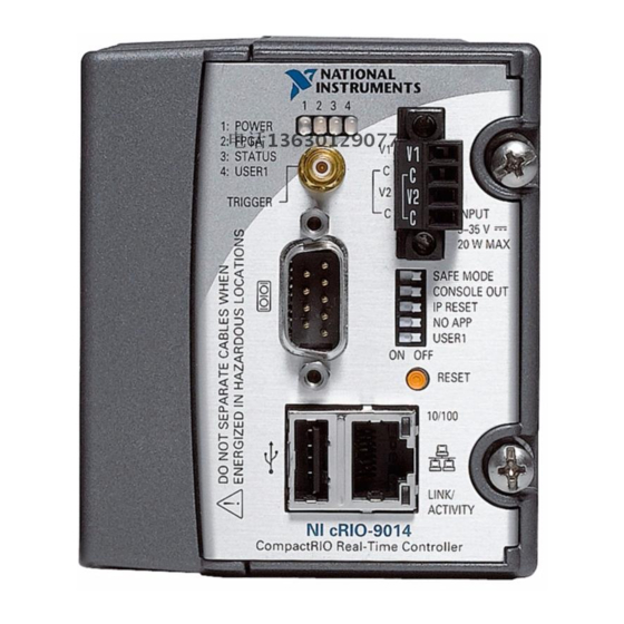
1. LEDs
2. SMB Connector
3. Power Connector
4. DIP Switches
This document describes how to connect the cRIO-9012/9014 to a network and how to use the
features of the cRIO-9012/9014. This document also contains specifications for the
controllers.
Safety Guidelines for Hazardous Locations
The cRIO-9012/9014 is suitable for use in Class I, Division 2, Groups A, B, C, D, T4
hazardous locations; Class I, Zone 2, AEx nA IIC T4 and Ex nA IIC T4 hazardous locations;
Figure 1. CompactRIO cRIO-9012/9014
1
7
2
5. Reset Button
6. RJ-45 Ethernet Port
7. USB Port
8. RS-232 Serial Port
3
4
5
6
Advertisement
Table of Contents

Related Manuals for NI cRIO-9012


Summary of Contents for NI cRIO-9012
- Page 1 Safety Guidelines for Hazardous Locations The cRIO-9012/9014 is suitable for use in Class I, Division 2, Groups A, B, C, D, T4 hazardous locations; Class I, Zone 2, AEx nA IIC T4 and Ex nA IIC T4 hazardous locations;...
-
Page 2: Special Conditions For Hazardous Locations Use In Europe And Internationally
II 3G and is suitable for use in Zone 2 hazardous locations, in ambient temperatures of -40 °C ≤ Ta ≤ 70 °C. If you are using the cRIO-9012/9014 in Gas Group IIC hazardous locations, you must use the device in an NI chassis that has been evaluated as Ex nC IIC T4, Ex IIC T4, Ex nA IIC T4, or Ex nL IIC T4 equipment. - Page 3 EMC performance is attained. Installing the Controller on the Chassis The following figure shows the dimensions of the cRIO-9012/9014. NI cRIO-9012/9014 User Manual and Specifications | © National Instruments | 3...
- Page 4 Complete the following steps to install the controller on the chassis. Make sure that no power is connected to the controller or the chassis. Align the controller with the chassis as shown in the following figure. 4 | ni.com | NI cRIO-9012/9014 User Manual and Specifications...
- Page 5 The host computer communicates with the controller over a standard Ethernet connection. If the host computer is on a network, you must configure the controller on the same subnet as the NI cRIO-9012/9014 User Manual and Specifications | © National Instruments | 5...
- Page 6 Installing the controller while power is applied to it can cause damage to the chassis. The cRIO-9012/9014 requires an external power supply that meets the specifications in the Power Requirements section. The cRIO-9012/9014 filters and regulates the supplied power and provides power for all of the I/O modules in the chassis.
- Page 7 Connecting Serial Devices to the cRIO-9012/9014 The cRIO-9012/9014 has an RS-232 serial port to which you can connect devices such as displays or input devices. Use the Serial VIs to read from and write to the serial port from a LabVIEW Real-Time application.
-
Page 8: Using The Internal Real-Time Clock
You can use the SMB connector of the cRIO-9012/9014 to connect digital devices to the controller. For example, if you connect the pulse-per-second output of a GPS device to the SMB connector of the cRIO-9012/9014, you can use the GPS device to correct for drift of the system clock. -
Page 9: Configuring Dip Switches
Keep this switch in the OFF position during normal operation. If the switch is in the ON position at startup, the cRIO-9012/9014 launches only the essential services required for updating its configuration and installing software. The LabVIEW Real-Time engine does not launch. -
Page 10: User1 Switch
2. FPGA 4. USER1 POWER LED The POWER LED is lit while the cRIO-9012/9014 is powered on. This LED indicates that the power supply connected to the chassis is adequate. 10 | ni.com | NI cRIO-9012/9014 User Manual and Specifications... - Page 11 You can use the FPGA LED to help debug your application or easily retrieve application status. Use the LabVIEW FPGA Module and NI-RIO software to define the FPGA LED to meet the needs of your application. Refer to LabVIEW Help for information about programming this LED.
-
Page 12: Rs-232 Serial Port
The following specifications are typical for the range -40 °C to 70 °C unless otherwise noted. Caution Do not operate the cRIO-9012/9014 in a manner not specified in this document. Product misuse can result in a hazard. You can compromise the safety protection built into the product if the product is damaged in any way. -
Page 13: Smb Connector
Info Code SSDBP DRAM cRIO-9012 64 MB cRIO-9014 128 MB Internal Real-Time Clock Accuracy 200 ppm; 35 ppm at 25 °C NI cRIO-9012/9014 User Manual and Specifications | © National Instruments | 13... -
Page 14: Power Requirements
After powerup 6 V to 35 V Note The cRIO-9012/9014 is guaranteed to power up when 9 V is applied to V and C. After powerup, it can operate on as little as 6 V. Maximum power input 20 W... -
Page 15: Safety Voltages
UL 60079-0; Ed 5, UL 60079-15; Ed 3 • CSA 60079-0:2011, CSA 60079-15:2012 Note For UL and other safety certifications, refer to the product label or the Online Product Certification section. NI cRIO-9012/9014 User Manual and Specifications | © National Instruments | 15... -
Page 16: Electromagnetic Compatibility
Refer to the manual for the chassis you are using for more information about meeting these specifications. Operating temperature -40 °C to 70 °C (IEC 60068-2-1, IEC 60068-2-2) Storage temperature -40 °C to 85 °C (IEC 60068-2-1, IEC 60068-2-2) 16 | ni.com | NI cRIO-9012/9014 User Manual and Specifications... -
Page 17: Environmental Management
For additional environmental information, refer to the Minimize Our Environmental Impact web page at ni.com/environment. This page contains the environmental regulations and directives with which NI complies, as well as other environmental information not included in this document. Waste Electrical and Electronic Equipment (WEEE) -
Page 18: Worldwide Support And Services
Pin 1 Pin 8 Worldwide Support and Services The NI website is your complete resource for technical support. At ni.com/support, you have access to everything from troubleshooting and application development self-help resources to email and phone assistance from NI Application Engineers. - Page 19 NI corporate headquarters is located at 11500 North Mopac Expressway, Austin, Texas, 78759-3504. NI also has offices located around the world. For telephone support in the United States, create your service request at ni.com/support or dial 1 866 ASK MYNI (275 6964). For telephone support outside the United States, visit the Worldwide Offices section of ni.com/...
- Page 20 . You can find information about end-user license agreements (EULAs) ni.com/patents and third-party legal notices in the readme file for your NI product. Refer to the Export Compliance Information at ni.com/ for the NI global trade compliance policy and how to obtain relevant HTS codes, ECCNs, and other legal/export-compliance import/export data.
Need help?
Do you have a question about the cRIO-9012 and is the answer not in the manual?
Questions and answers