Table of Contents
Advertisement
GETTING STARTED GUIDE
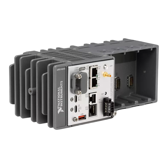
cRIO-904x
Embedded CompactRIO Controller with Real-Time Processor and
Reconfigurable FPGA
This document describes how to begin using the cRIO-904x.
In this document, the cRIO-9040, cRIO-9041, cRIO-9042, cRIO-9043, cRIO-9045,
cRIO-9046, cRIO-9047, cRIO-9048, and cRIO-9049 are referred to collectively as cRIO-904x.
Note
Refer to the device Safety, Environmental, and Regulatory Information
document, shipped with your cRIO-904x controller and available on
manuals, for important safety and environmental specifications necessary when
setting up your device.
Unpacking the Kit
Notice
To prevent electrostatic discharge (ESD) from damaging the device, ground
yourself using a grounding strap or by holding a grounded object, such as your
computer chassis.
1.
Touch the antistatic package to a metal part of the computer chassis.
2.
Remove the device from the package and inspect the device for loose components or any
other sign of damage.
Notice
Note
3.
Unpack any other items and documentation from the kit.
Store the device in the antistatic package when the device is not in use.
Never touch the exposed pins of connectors.
Do not install a device if it appears damaged in any way.
ni.com/
Advertisement
Table of Contents

Related Manuals for NI cRIO-904 Series


Summary of Contents for NI cRIO-904 Series
- Page 1 Note Refer to the device Safety, Environmental, and Regulatory Information document, shipped with your cRIO-904x controller and available on ni.com/ manuals, for important safety and environmental specifications necessary when setting up your device. Unpacking the Kit...
-
Page 2: What You Need To Get Started
Installing Software on the Host Computer If you do not currently have any NI software installed on your host computer, see the Install Software section for details on required software and in which order to install it. If you have some NI software already installed, see the Software Compatibility Resources section for resources to check the compatibility of your software with your controller. - Page 3 NI CompactRIO Device Drivers 17.6 and later include NI-DAQmx driver software. To deploy C Series modules installed in the cRIO-904x in Real-Time (NI-DAQmx) mode, ensure that NI- DAQmx is selected during installation. To deploy C Series modules installed in the cRIO-904x in Real-Time Scan (IO Variables) mode, ensure that NI Scan Engine is selected during installation.
-
Page 4: Installing The C Series Modules
Align the C Series module with a slot and seat it in the slot until the latches lock in place. Connecting the cRIO-904x The cRIO-904x has the following connectors, LEDs, and buttons. For a full description of all front panel features, see the cRIO-904x User Manual. 4 | ni.com | cRIO-904x Getting Started Guide... -
Page 5: Connecting The Controller To Ground
Figure 2. cRIO-904x Front Panel 1. LEDs 8. RS-232 Serial Port 2. RJ-45 Gigabit Ethernet Ports 9. RS-485 Serial Port 3. USER1 Button 10. USB 2.0 Type-A 4. PFI 0 11. USB 3.1 Type-C with DisplayPort Alt Mode 5. RESET Button 12. - Page 6 Solder the other end of the wire to the cable shield. Use shorter wire for better EMC performance. For more information about ground connections, visit ni.com/info and enter the Info Code emcground 6 | ni.com | cRIO-904x Getting Started Guide...
-
Page 7: Connecting The Controller To Power
Primary power supply, 9 V to 30 V, 60 W minimum • (Optional) Secondary power supply, 9 V to 30 V, 60 W minimum NI recommends the power supplies listed in the following table for the cRIO-904x. Table 2. NI Power Supplies Power Supply... - Page 8 Figure 4. Power Screw Terminal Connector Plug 1. Terminal Screw 2. Connector Screw Flanges Connect the primary power supply and optional secondary power supply to the power connector, as shown in the following figure. 8 | ni.com | cRIO-904x Getting Started Guide...
-
Page 9: Connecting The Controller To The Host Computer
Figure 5. cRIO-904x Power Connections – Primary Power Supply – Secondary Power Supply Power Connector Note The C terminals are internally connected to each other. Tighten the terminal screws on the power connector to 0.20 N · m to 0.25 N · m (1.8 lb ·... -
Page 10: Discovering The Controller In Max
If the device driver software does not detect the cRIO-904x, verify that you installed the appropriate NI software in the correct order on the host computer as described in Installing Software on the Host Computer. Discovering the Controller in MAX Complete the following steps to find the cRIO-904x controller in MAX. -
Page 11: Setting A System Password
Click the OK button. Click the Set Permissions button in the toolbar. The NI Web-Based Configuration and Monitoring utility opens in your default browser and is where you set the password. If you have not installed Microsoft Silverlight, NI Web-based Configuration & Monitoring prompts you to do so. -
Page 12: Installing Software On The Controller
To set a password for your system, refer to Setting a System Password. Select the recommended software set for your LabVIEW and NI-RIO Device Drivers versions. Click Next. Select any additional software from the list of software add-ons, if needed. -
Page 13: Testing Your Controller In Max
Note LabVIEW FPGA Module is required to run your modules in the LabVIEW FPGA program mode. NI Scan Engine is required to run your modules in the Real-Time Scan (IO Variables) program mode. Click Next. Verify that the summary of software to install is correct. - Page 14 Configure the measurement settings and click Start. 14 | ni.com | cRIO-904x Getting Started Guide...
-
Page 15: Changing Module Programming Modes In Max
Changing Module Programming Modes in MAX Complete the following steps to deploy your C Series module in a new program mode in MAX. Launch MAX on the host computer. Expand Remote Systems in the configuration tree and locate your cRIO-904x system. Select the C Series module you wish to program. - Page 16 Click Save. The module is deployed in the program mode. Notice the module icon changes to represent the program mode. 1. Real-Time Mode 2. Real-Time Scan (IO Variables) Mode 3. LabVIEW FPGA Mode 16 | ni.com | cRIO-904x Getting Started Guide...
-
Page 17: Troubleshooting The Controller
. The host computer communicates with the cRIO-904x over a standard Ethernet connection. • Ensure that you have the correct version of NI CompactRIO Device Drivers installed on the host computer. Visit ni.com/info and enter the Info Code for the swsupport minimum supported versions of LabVIEW and NI CompactRIO Device Drivers. -
Page 18: System Reset
Press and hold RESET button for < 5 s • Network settings reset Safe Mode • RT Startup App disabled • FPGA Startup App disabled Press and hold RESET button for ≥ 5 s 18 | ni.com | cRIO-904x Getting Started Guide... -
Page 19: Status Led Indicators
The cRIO-904x is in safe mode. The software has crashed and pauses twice without rebooting or cycling power between crashes. Continuously The cRIO-904x has not booted into NI Linux Real-Time. blinks The cRIO-904x either booted into an unsupported operating system, was interrupted during the boot process, or detected an unrecoverable software error. -
Page 20: Using The Crio-904X In Labview
Complete the following steps to create a new LabVIEW project configured with the cRIO-904x controller. You can use LabVIEW to program in Real-Time (NI-DAQmx) or Real-Time Scan (IO Variables) modes. For applications using advanced functionality that require programming the FPGA, LabVIEW FPGA Module is required to deploy C Series modules in the LabVIEW... - Page 21 FPGA program mode. Refer to the Adding the cRIO-904x to a LabVIEW FPGA Project more information. Refer to "Choosing Your Programming Mode" in the cRIO-904x User Manual to determine which programming modes are right for your application. To create a new LabVIEW project, launch LabVIEW and click Create Project. Select Blank Project from the Create Project dialog and click Finish.
- Page 22 Measurement & Automation Explorer. If your system is on a remote subnet, you can also select to manually enter the IP address. You can locate the system IP address in MAX in the System Settings for the cRIO-904x. 22 | ni.com | cRIO-904x Getting Started Guide...
-
Page 23: Deploying Your C Series Module In A Programming Mode In Labview
Real-Time (NI-DAQmx) programming mode. Right-click the cRIO-904x in the project and select Deploy All to deploy the module in the Real-Time (NI-DAQmx) programming mode. Your module is now in Real-Time (NI-DAQmx) mode. cRIO-904x Getting Started Guide | © National Instruments | 23... -
Page 24: Adding The Crio-904X To A Labview Fpga Project
LabVIEW FPGA Module is required to program the user-accessible FPGA on the cRIO-904x or deploy C Series modules in the LabVIEW FPGA program mode. To program in Real-Time (NI-DAQmx) or Real-Time Scan (IO Variables) modes, the LabVIEW FPGA module is not required. Refer to Adding the cRIO-904x to a LabVIEW Project for more information. - Page 25 Enter the IP address for the cRIO-904x and click Next. Note You can locate the system IP address in MAX in the System Settings for the cRIO-904x. In the LabVIEW Project Explorer, verify that your system is present in the project tree and click Finish.
- Page 26 Right-click the cRIO-904x in the project and select Deploy All to deploy the module in the Real-Time (NI-DAQmx) programming mode. Your module is now in Real-Time (NI-DAQmx) mode. Programming Examples For information on getting started with DAQmx programming mode examples in LabVIEW FPGA, go to ni.com/info...
-
Page 27: Where To Go Next
NI. NI corporate headquarters is located at 11500 North Mopac Expressway, Austin, Texas, 78759-3504. NI also has offices located around the world. For support in the United States, create your service request at ni.com/support... - Page 28 (EULAs) and third-party legal notices in the readme file for your NI product. NI MAKES NO EXPRESS OR IMPLIED WARRANTIES AS TO THE ACCURACY OF THE INFORMATION CONTAINED HEREIN AND SHALL NOT BE LIABLE FOR ANY ERRORS. U.S. Government Customers: The data contained in this manual was developed at private expense and is subject to the applicable limited rights and restricted data rights as set forth in FAR 52.227-14, DFAR 252.227-7014, and DFAR 252.227-7015.
Need help?
Do you have a question about the cRIO-904 Series and is the answer not in the manual?
Questions and answers