
Subscribe to Our Youtube Channel
Related Manuals for NI 7931R


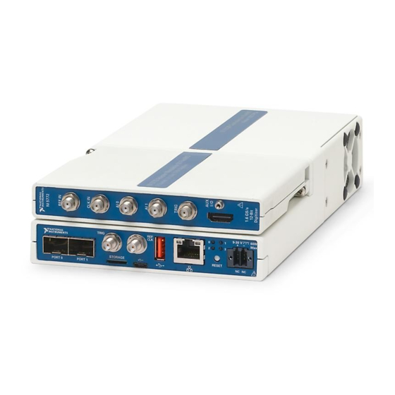
Summary of Contents for NI 7931R
- Page 1 FlexRIO NI-7931R/7932R/7935R User Manual NI-793xR User Manual August 2015 375181B-01...
- Page 2 National Instruments Corporate Headquarters 11500 North Mopac Expressway Austin, Texas 78759-3504 USA Tel: 512 683 0100 For further support information, refer to the NI Services appendix. To comment on National Instruments documentation, refer to the National Instruments website at ni.com/info...
- Page 3 You must obtain an RMA number from NI before returning any product to NI. NI reserves the right to charge a fee for examining and testing Hardware not covered by the Limited Warranty.
- Page 4 LEAD TO DEATH, PERSONAL INJURY, SEVERE PROPERTY DAMAGE OR ENVIRONMENTAL HARM (COLLECTIVELY, “HIGH-RISK USES”). FURTHER, PRUDENT STEPS MUST BE TAKEN TO PROTECT AGAINST FAILURES, INCLUDING PROVIDING BACK-UP AND SHUT-DOWN MECHANISMS. NI EXPRESSLY DISCLAIMS ANY EXPRESS OR IMPLIED WARRANTY OF FITNESS OF THE PRODUCTS OR SERVICES FOR HIGH-RISK...
- Page 5 The Declaration of Conformity (DoC) contains important EMC compliance information and instructions for the user or installer. To obtain the DoC for this product, visit , search by ni.com/certification model number or product line, and click the appropriate link in the Certification column.
-
Page 6: Table Of Contents
Before You Begin Development Requirements ..................... 1-1 Xilinx Licensing Information ................... 1-2 Chapter 2 Mounting the NI-793xR Mounting the NI-793xR Directly on a Flat Surface ..........2-3 Installing the Rubber Feet..................2-4 Chapter 3 Hardware Architecture NI-7931R .......................... 3-1 NI-7931R Key Features.................... 3-4 Clocking Architecture.................... - Page 7 Documenting Your IP..................5-9 Adding MGT Socketed CLIP to the LabVIEW Project ...........5-9 Configuring MGT Socketed CLIP in the NI-793xR LabVIEW FPGA Targets..5-10 Using Existing VHDL IP inside CLIP or IPIN............5-11 Improving Performance in Larger Designs through Enable Chain Removal ... 5-11...
- Page 8 NI-793xR User Manual Appendix A CLIP Signals Appendix B Using the Fan Appendix C NI Services Glossary © National Instruments | ix...
-
Page 9: About This Manual
About This Manual The NI-7931R/7932R/7935R User Manual describes how to use the NI-7931R, NI-7932R, and NI-7935R controllers for FlexRIO to develop high-performance embedded applications. This manual provides detailed information about the electrical and mechanical requirements of component-level IP (CLIP) and LabVIEW FPGA design. - Page 10 Available at Contains information ni.com/ Module Release and . You can also view about installing the manuals Upgrade Notes this document by selecting LabVIEW FPGA Module, Start»All Programs»National describes new features, and Instruments»LabVIEW» provides upgrade information. LabVIEW Manuals. xii | ni.com...
-
Page 11: Xilinx Documentation
NI-793xR User Manual Xilinx Documentation Xilinx FPGA documentation provides information required for the successful development of your controller for FlexRIO. The following table provides a list of specific Xilinx documentation resources. Table 2. Xilinx Documentation Document Document Part Number Description... -
Page 12: Additional Resources
DRAM interfaces, and trigger logic, along with the associated host APIs. LabVIEW examples Available in NI Example Finder. Contains examples of how to In LabVIEW, click Help»Find run FPGA VIs and Host VIs Examples»Hardware Input on your device. -
Page 13: Before You Begin
This section contains information you need before developing high-performance embedded applications using the NI-7931R, NI-7932R, and NI-7935R devices. Development Requirements Successful system design with the NI-793xR devices may require knowledge in the following areas, depending on your application. • Real-time programming •... -
Page 14: Xilinx Licensing Information
Chapter 1 Before You Begin Xilinx Licensing Information Refer to the Xilinx Documentation section of About This Manual for a list of Xilinx documentation that contains important Xilinx licensing information. 1-2 | ni.com... -
Page 15: Mounting The Ni-793Xr
In order to obtain the maximum allowable ambient temperature as Caution specified in your device’s specifications document, you must maintain at least 1 in. of clearance on either side of the NI-793xR. Refer to Figure 2-1 for fan clearance information. Figure 2-1. Fan Clearance... - Page 16 Chapter 2 Mounting the NI-793xR You can mount the NI-793xR in a variety of configurations. The following table lists the ecommended mounting methods. Table 2-1. Mounting Options Method Required Accessory Kit NI Part Number Direct mounting — — Panel Panel Mount Accessory Kit 784365-01 The following sections contain instructions for the mounting methods.
-
Page 17: Mounting The Ni-793Xr Directly On A Flat Surface
NI-793xR User Manual Mounting the NI-793xR Directly on a Flat Surface For applications sensitive to shock and vibration, NI recommends mounting the device directly on a flat, rigid surface using the mounting holes in the device. You will need the following items to mount the device directly on a flat surface: •... -
Page 18: Installing The Rubber Feet
Mounting the NI-793xR Installing the Rubber Feet The NI-793xR ships with optional rubber feet. Install the rubber feet to the bottom of the device, as shown in Figure 2-3. Do not install rubber feet when directly mounting the NI-793xR. The Caution rubber feet will prevent full contact between the unit and the mounting surface. -
Page 19: Hardware Architecture
10 FlexRIO adapter module connector Refer to Figure 3-2 for LED placement. † Refer to the NI-7931R Getting Started Guide for instructions about how to wire power to the NI-7931R. ‡ Refer to Figure 3-3 for the pinout. © National Instruments | 3-1... - Page 20 Chapter 3 Hardware Architecture The following figure shows the NI-7931R LEDs in more detail. Figure 3-2. NI-7931R LEDs Power Status FPGA User RT User 3-2 | ni.com...
- Page 21 NI-793xR User Manual The following figure shows the available signals on the NI-7931R adapter module connector. Figure 3-3. NI-7931R FPGA Connector Pinout Secondary Side Primary Side Secondary Side Primary Side +3.3V +3.3V S148 GPIO_CC_38_n S114 GPIO_CC_14_n TB_Power_Good S147 TB_Present_n GPIO_CC_38...
-
Page 22: Ni-7931R Key Features
Chapter 3 Hardware Architecture NI-7931R Key Features The NI-7931R device includes the following key features. Refer to the NI-7931R Specifications for more details. • Kintex-7 XC7K325T FPGA • 2 GB onboard FPGA-accessible DRAM • NI Linux Real-Time (32-bit) controller •... -
Page 23: Clocking Architecture
NI-793xR User Manual Clocking Architecture The NI-7931R device includes dedicated clocking hardware to provide a flexible clocking solution for your FlexRIO system. Refer to Chapter 4, Developing with LabVIEW FPGA, for information about configuring clocks with LabVIEW FPGA. The NI-7931R clocking architecture includes the following clocks: •... -
Page 24: Ni-7932R
11 SFP+ connectors 1 Gb Ethernet Refer to Figure 3-7 for LED placement. † Refer to the NI-7932R Getting Started Guide for instructions about how to wire power to the NI-7932R. ‡ Refer to Figure 3-8 for the pinout. 3-6 | ni.com... - Page 25 NI-793xR User Manual The following figure shows the NI-7932R LEDs in more detail. Figure 3-7. NI-7932R LEDs Status Power FPGA User RT User © National Instruments | 3-7...
- Page 26 Chapter 3 Hardware Architecture The following figure shows the available signals on the NI-7932R adapter module connector. Figure 3-8. NI-7932R FPGA Connector Pinout Secondary Side Primary Side Secondary Side Primary Side +3.3V +3.3V S148 GPIO_CC_38_n S114 GPIO_CC_14_n TB_Power_Good S147 TB_Present_n...
-
Page 27: Ni-7932R Key Features
NI-793xR User Manual NI-7932R Key Features The NI-7932R device includes the following key features. Refer to the NI-7932R Specifications for more details. • SFP+ line rates of 3.125 Gbps, 6.25 Gbps, and 10.3125 Gbps • Kintex-7 XC7K325T FPGA • 2 GB onboard FPGA-accessible DRAM •... - Page 28 Chapter 3 Hardware Architecture The following figure illustrates the key components of the NI-7932R architecture. Figure 3-9. NI-7932R Architecture Key Components Controller RT Host 1 Gig E LabVIEW NV Storage RT Clock Host VI Watch Dog Interrupts Controls/Indicators NI-Defined Bus...
-
Page 29: Clocking Architecture
NI-793xR User Manual Clocking Architecture The NI-7932R device includes dedicated clocking hardware to provide a flexible clocking solution for your FlexRIO system. Refer to Chapter 4, Developing with LabVIEW FPGA, for information about configuring clocks with LabVIEW FPGA. The NI-7932R clocking architecture includes the following clocks: •... -
Page 30: Ni-7935R
11 SFP+ connectors 1 GB Ethernet Refer to Figure 3-12 for LED placement. † Refer to the NI-7935R Getting Started Guide for instructions about how to wire power to the NI-7935R. ‡ Refer to Figure 3-13 for the pinout. 3-12 | ni.com... - Page 31 NI-793xR User Manual The following figure shows the NI-7935R LEDs in more detail. Figure 3-12. NI-7935R LEDs Status Power FPGA User RT User © National Instruments | 3-13...
- Page 32 Chapter 3 Hardware Architecture The following figure shows the available signals on the NI-7935R adapter module connector. Figure 3-13. NI-7935R FPGA Connector Pinout Secondary Side Primary Side Secondary Side Primary Side +3.3V +3.3V S148 GPIO_CC_38_n S114 GPIO_CC_14_n TB_Power_Good S147 TB_Present_n...
-
Page 33: Ni-7935R Key Features
NI-793xR User Manual NI-7935R Key Features The NI-7935R device includes the following key features. Refer to the NI-7935R Specifications for more details. • SFP+ line rates of 3.125 Gbps, 6.25 Gbps, and 10.3125 Gbps • Kintex-7 XC7K410T FPGA • 2 GB onboard FPGA-accessible DRAM •... -
Page 34: Clocking Architecture
Chapter 3 Hardware Architecture Clocking Architecture The NI-7935R device includes dedicated clocking hardware to provide a flexible clocking solution for your FlexRIO system. Refer to Chapter 4, Developing with LabVIEW FPGA, for information about configuring clocks with LabVIEW FPGA. The NI-7935R clocking architecture includes the following clocks: •... - Page 35 NI-793xR User Manual The following figure illustrates the clocking circuitry on the NI-7935R. Figure 3-15. NI-7935R Clocking Diagram Adapter Module IoModSyncClock Kintex-7 FPGA 10 MHz Reference Clock 40 MHz 100 MHz 156.25 MHz/ 200 MHz 312.5 MHz DRAM Clock Memory...
-
Page 36: Developing With Labview Fpga
LabVIEW on your host computer for a fully integrated development experience. Refer to the NI LabVIEW High-Performance FPGA Developer’s Guide for information about techniques to optimize throughput, latency, and FPGA resources. Refer to the Related... -
Page 37: Adding Items To The Ni-793Xr Target
Explorer window. Adding NI-793xR Target I/O Complete the following steps to add target I/O for the NI-793xR and to access signals from any instantiated CLIP on the block diagram: Place an FPGA I/O node on the FPGA target block diagram. The FPGA I/O node is located on the palette under Functions»FPGA I/O»FPGA I/O Node. -
Page 38: Auto-Loading Bitfiles On Power-Up
High-Performance LabVIEW FPGA Developer’s Guide. Auto-loading Bitfiles on Power-up You can configure the NI-793xR to auto-load a bitfile on power-up, or you can use a startup executable on the Real-Time controller to load a specific bitfile when the device powers up. -
Page 39: Using The Ni Common Instrument Design Libraries
Execution Mode. Using the NI Common Instrument Design Libraries NI provides instrument design libraries that you can use to create application-specific instrumentation designs for NI-793xR devices. The following sections provide an overview of the instrument design libraries. The instrument design libraries are located at <LVDir>\... -
Page 40: Basic Elements Overview
The NI-793xR targets include large FPGA devices that require a 64-bit compile worker. Refer to the FlexRIO Support Readme for more information about what platforms to use to compile bitfiles. You cannot add additional licenses to remote compile workers in the NI LabVIEW FPGA Compile Cloud Service. -
Page 41: Streaming
FPGA-to-Host FIFO uses Ready for Input signals to communicate to the DRAM whether it is ready to process more data. The following figure demonstrates how you can implement flow control on an NI-793xR target. Figure 4-1. Host-Side FIFO to FPGA Flow Control... -
Page 42: Dma Streaming
The NI-793xR provides up to 16 DMA channels that can be accessed by your Host. These channels can be used in a variety of ways to meet your application’s needs. The total overall bandwidth of the device limits your DMA use, whether you use 1 DMA channel or 16. -
Page 43: Simulating Fpga Behavior
Developing with LabVIEW FPGA Simulating FPGA Behavior You can simulate an FPGA VI that has been added to an NI-793xR target; however, you cannot open a reference to the simulated FPGA VI from the NI-793xR target. Instead, you must open a reference to the simulated FPGA VI by changing the application instance to My Computer. -
Page 44: Programming The High-Speed Serial Ports
LabVIEW. The NI-7931R does not have MGTs or high-speed serial ports. Note Development Flow Refer to the following diagram for an overview of the NI-793xR development process for implementing a high-speed serial protocol. Figure 5-1. NI-793xR Development Process Start Update LabVIEW... -
Page 45: Developing Mgt Socketed Clip
Allows your IP to communicate directly with both the FPGA VI and the external adapter module connector interface. Socketed CLIP Architecture Figure 5-2 shows an overview of the NI-7932R socketed CLIP interface. Figure 5-3 shows an overview of the NI-7935R socketed CLIP interface. Figure 5-2. NI-7932R Socketed CLIP Architecture NI-7932R 156.25 MHz/... -
Page 46: Accessing The Xilinx Vivado Tools
NI-793xR User Manual Figure 5-3. NI-7935R Socketed CLIP Architecture NI-7935R 156.25 MHz/ Xilinx Kintex-7 FPGA 312.5 MHz Clock Socketed CLIP LabVIEW FPGA VI High-Speed Serial MGT_RefClks Protocol IP PORT 0 / LabVIEW FPGA Xilinx GTXE2_CHANNEL/ High Speed PORT 1 GTXE2_COMMON... -
Page 47: Generating An Ip Core From The Xilinx Vivado Ip Catalog
Aurora 64B66B IP core is located in Communication and Networking»Serial Interfaces»Aurora 64B66B. Select the IP core settings. NI recommends that you select AXI4-Stream for high-speed data streams when possible. NI does not recommend selecting AXI4-Lite for DRP accesses in the Xilinx... -
Page 48: Building A Netlist From The Ip Core
NI-793xR User Manual Do not modify the IP core unless you understand the required reference Note clock(s) and clocking resources. The following figure shows the difference between the top-level CLIP VHDL with shared logic in the core (left) and without shared logic (right). - Page 49 You may have to specify a longer path name depending on the location of the Note cell in your project. For example, clock_module_i may be located under aurora_64b66b_0_block_i/clock_module_i Copy the netlist into your LabVIEW FPGA CLIP directory. Include your netlist in the list of synthesis files when running the CLIP Wizard. 5-6 | ni.com...
-
Page 50: Writing A Vhdl Wrapper Around The Protocol Ip Core
A VHDL wrapper is generally necessary to adapt the protocol signals to the dataflow semantics used within the LabVIEW FPGA diagram. NI recommends that you adhere to the following guidelines when writing a VHDL wrapper around the protocol IP core: •... -
Page 51: Constraints And Hierarchy
In order to guarantee data integrity and timing closure, verify that I/O Caution nodes from the CLIP are written in the same clock domain in which they are read on the LabVIEW diagram and that I/O nodes to the CLIP are read in the same clock 5-8 | ni.com... -
Page 52: Documenting Your Ip
Note that data corruption might still occur when crossing clock domains. Documenting Your IP NI recommends documenting the behavior of your CLIP. Refer to the following guidelines for information about how to document your CLIP and how documenting your CLIP can affect the rest of your design: •... -
Page 53: Configuring Mgt Socketed Clip In The Ni-793Xr Labview Fpga Targets
Programming the High-Speed Serial Ports Configuring MGT Socketed CLIP in the NI-793xR LabVIEW FPGA Targets Complete the following steps to configure MGT Socketed CLIP in your NI-793xR LabVIEW project: Create a new project by selecting File»New»Project, or open an existing project by selecting File»Open. -
Page 54: Using Existing Vhdl Ip Inside Clip Or Ipin
12. Click OK. Refer to Chapter 3, Hardware Architecture, for more information about NI-793xR clocking capabilities. Using Existing VHDL IP inside CLIP or IPIN To use existing IP in your project, refer to the Importing External IP Into LabVIEW FPGA white paper at ni.com... -
Page 55: Programming With The Real-Time Target
RTOS performs has a known maximum completion time. By designing an application for an RTOS, you can make sure an application will run deterministically. • RT target—A controller, such as an NI-793xR, that runs an RTOS. • Stand-alone RT application—An RT application that runs automatically when you power on an RT target. -
Page 56: Installing And Configuring The Ni-793Xr
Installing and Configuring the NI-793xR Refer to the getting started guide for your NI-793xR for instructions about how to perform the following tasks before developing a real-time application for your NI-793xR: Install support for the NI-793xR on the host computer. -
Page 57: Real-Time System Integration
The NI-793xR includes four temperature sensors and one fan. Three of the temperature sensors monitor the CPU, and one temperature sensor monitors the FPGA. Refer to the following table for the resource you must use to access each temperature sensor and fan, as well as each component’s operating range. -
Page 58: Power/Thermal Protection And Shutdown
FPGA do not work. Additionally, a device status message appears in MAX under the FPGA item that has been shut down. If the FPGA communication shuts down, power cycle the system and contact NI customer support at . In order to ni.com/support... -
Page 59: Communicating With Applications On An Rt Target
Open the Property Node (Hardware) to obtain information such as the device temperature and device model name. Refer to the NI System Configuration API Help topic of the LabVIEW Help for more information about using the LabVIEW System Configuration API. For information about the FlexRIO System Configuration API, refer to the FlexRIO System Configuration Expert topic in the FlexRIO Help. -
Page 60: Network Communication
The Interacting with the Front Panels of RT Target VIs topic in the Note LabVIEW Real-Time Module Help contains information about an embedded UI, which is not available on NI-793xR targets. Where to Go from Here The Real-Time Module includes a comprehensive documentation set designed to help you create deterministic applications to run on RT targets. -
Page 61: Labview Real-Time Module Release And Upgrade Notes
NI-793xR User Manual • Real-Time Operating Systems—Information about using LabVIEW on real-time operating systems. • Real-Time Module Error Codes—Information about error codes specific to the Real-Time Module. LabVIEW Real-Time Module Release and Upgrade Notes The LabVIEW Real-Time Module Release and Upgrade Notes contains information to help you install and configure the Real-Time Module and a list of upgrade issues and new features. - Page 62 CLIP Signals This chapter contains lists of CLIP signals for the NI-7932R and NI-7935R devices. NI-7932R Refer to the following table for a list of the NI-7932R socketed CLIP signals. Table A-1. NI-7932R CLIP Signals Port Direction Clock Domain Description...
- Page 63 Appendix A CLIP Signals Table A-1. NI-7932R CLIP Signals (Continued) Port Direction Clock Domain Description aResetSl Async This signal is not required. This signal is an asynchronous reset signal from the LabVIEW FPGA environment. If you create an input signal to...
- Page 64 NI-793xR User Manual Table A-1. NI-7932R CLIP Signals (Continued) Port Direction Clock Domain Description Port<0..1>_Tx_ Async When high, this output shuts Disable down the transmitter optical transmitter. When low, operation is enabled. Port<0..1>_Rs<0..1> Async Rate selection pins. Port<0..1>_SCL In/Out Async...
- Page 65 Port <0..1> is enabled. This signal may deassert if an over-power condition is detected. NI-7935R Refer to the following table for a list of the NI-7935R socketed CLIP signals. Table A-2. NI-7935R CLIP Signals Port Direction Clock Domain Description...
- Page 66 NI-793xR User Manual Table A-2. NI-7935R CLIP Signals (Continued) Port Direction Clock Domain Description aResetSl Async This signal is not required. This signal is an asynchronous reset signal from the LabVIEW FPGA environment. If you create an input signal to...
- Page 67 Appendix A CLIP Signals Table A-2. NI-7935R CLIP Signals (Continued) Port Direction Clock Domain Description Port<0..1>_Tx_ Async When high, this output shuts Disable down the transmitter optical transmitter. When low, operation is enabled. Port<0..1>_Rs<0..1> Async Rate selection pins. Port<0..1>_SCL In/Out...
- Page 68 NI-793xR User Manual Table A-2. NI-7935R CLIP Signals (Continued) Port Direction Clock Domain Description sPort<0..1>_ SocketClk40 Enables or disables the power EnablePower supply to Port <0..1>. This signal is active high. sPort<0..1>_ SocketClk40 Indicates that the power supply PowerGood to the cable for Port <0..1> is enabled.
- Page 69 Using the Fan The NI-793xR includes a low power consumption DC fan for cooling the device. The following table lists the fan specifications. Table B-1. NI-793xR Fan Specifications Manufacturer Sanyo Denki Manufacturer part number 9GA0412G7001 Rated voltage 12 V Operating voltage range 7 V to 13.8 V...
- Page 70 – Warranty and Repair—All NI hardware features a one-year standard warranty that is extendable up to five years. NI offers repair services performed in a timely manner by highly trained factory technicians using only original parts at a National Instruments service center.
- Page 71 KnowledgeBase, product manuals, step-by-step troubleshooting wizards, thousands of example programs, tutorials, application notes, instrument drivers, and so on. Registered users also receive access to the NI Discussion Forums . NI Applications Engineers make sure every question submitted ni.com/forums...
- Page 72 Double data rate. This term usually refers to the communication mechanism used to read and write DRAM. DRAM Dynamic random-access memory FPGA Field-programmable gate array. NI-793xR modules use Xilinx Kintex-7 FPGAs. GPIO General-purpose input/output Hardware-description language. Language that describes a circuit’s operation, design, and organization. LVFPGA LabVIEW FPGA Multi-gigabit transceiver.
- Page 73 Glossary Programmable function interface SCTL Single cycle timed loop SFP+ Enhanced small form-factor pluggable VHDL VHSIC Hardware Description Language G-2 | ni.com...
Need help?
Do you have a question about the 7931R and is the answer not in the manual?
Questions and answers