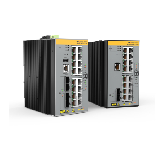
Allied Telesis IE340-12GP Quick Installation Manual
Industrial ethernet layer 3 switches
Hide thumbs
Also See for IE340-12GP:
- Installation manual (136 pages) ,
- Quick installation manual (4 pages) ,
- Command reference manual (3474 pages)
Table of Contents
Advertisement
Quick Links
Quick Installation Guide
IE340-12GP, IE340-12GT, and IE340-20GP
Industrial Ethernet Layer 3 Switches
Installation and User's Guides
This document contains an abbreviated version of the installation instructions for the
IE340-12GP, IE340-12GT, and IE340-20GP switches. For complete installation instructions
and safety statements, see the IE340 Series Installation Guide on the Allied Telesis web
site at www.alliedtelesis.com/support.
Safety and Electromagnetic Emissions Certificates
For Safety and Electromagnetic Emissions certificates, see the IE340 Series Installation
Guide.
Informationen zu Sicherheitszertifikaten und Zertifikaten für elektromagnetische
Emissionen finden Sie im Installationshandbuch für die Serie IE340.
Para obtener los certificados de seguridad y emisiones electromagnéticas, consulte la
Guía de instalación de la serie IE340.
Pour les certificats relatifs à la sécurité et aux émissions électromagnétiques, consultez le
Guide d'installation de la série IE340.
Per i certificati di sicurezza ed emissioni elettromagnetiche, consultare la Guida
all'installazione della serie IE340.
Сертификаты безопасности и электромагнитного излучения см. В Руководстве по
установке серии IE340.
U.S. Federal Communications Commission
This device complies with Part 15 of FCC Rules. Operation is subject to the following two
conditions: (1) this device may not cause harmful interference, and (2) this device must
accept any interference received, including interference that may cause undesired
operation.
VCCI Statements
この装置は、クラスA情報処理装置です。この装置を家庭環境で使用すると電波妨害を
引き起こすことがあります。この場合には使用者が適切な対策を講ずるよう要求される
ことがあります。VCCI-A
Industrial Canada
This Class A digital apparatus complies with Canadian ICES-003.
Cet appareil numérique de la classe A est conforme à la norme NMB-003 du Canada.
Note for Indoor Installations
There are some specific installation requirements associated with the safety standards.
All indoor installations shall require a UL Listed or Nationally Recognized Test Lab
(NRTL) enclosure to meet safety requirements for Electrical Equipment For
Measurement, Control, and Laboratory Use referenced in the standards listed in the
IE340 Series Installation Guide.
Physical Description
For physical descriptions of the IE340 series switches, see the IE340 Series Installation
Guide.
*613-002782 Rev D*
613-002782 Rev. D
Package Contents
The following items should be in the shipping containers:
One IE340-12GP, IE340-12GT, or IE340-20GP switch
This Quick Installation Guide
One dust cover on the USB port (pre-installed)
Dust covers for the twisted pair ports and Console port (pre-installed)
–
Seventeen dust covers for the IE340-20GP switch
–
Nine dust covers for the IE340-12GP and IE340-12GT switches
Four dust covers on the SFP slots (pre-installed)
One 4-pin connector on the DC input power terminal block (PWR 1 and PWR 2)
Two 2-pin connectors on the alarm terminal blocks (ALM IN and ALM OUT)
One DIN rail mount bracket (pre-installed)
Two wall mount brackets
One M4x8 Phillips-head grounding screw
Five M4x8 Phillips-head screws
If any item is missing or damaged, contact your Allied Telesis sales representative for
assistance. Retain the original shipping material in case you need to return the unit to
Allied Telesis.
Installation Options
This quick installation guide explains how to install the device on a DIN rail, a plywood
base wooden wall, or concrete wall. For outdoor installations, refer to the IE340 Series
Installation Guide.
Installing the Switch on DIN Rail
To install the switch on a DIN rail, perform the following procedure:
1.
Hold the switch with both hands facing toward the DIN rail on the wall.
2.
Tilt the bottom of the switch towards the wall and hook the bottom of the switch
bracket on the bottom edge of DIN rail.
3.
While pressing the switch upwards to compress the springs of the bracket, hook the
top of the bracket on the DIN rail by pushing the top of the switch toward the wall
until it is vertical.
4.
Visually inspect the bracket to verify that the DIN rail is now fitted into the top and
bottom slots.
Note
Allied Telesis recommends installing DIN rail end clamps to the sides of the switch
to prevent damage or network traffic loss from vibration or shock. End clamps are
not available from Allied Telesis.
1
Installing the Switch on a Plywood Base Wooden Wall
Allied Telesis recommends using a plywood base when installing the switch on the wall with
wooden studs. The base allows you to mount the device on two studs in the wall. First,
install the plywood base to the wall.
Wall Studs
Wall
Plywood
Base
To install the switch on the plywood base, perform the following procedure:
Note
The switch's maximum operating temperature depends on its orientation on the wall
and the type of enclosure. Allied Telesis recommends installing the device vertically
for best possible airflow and cooling. See the above figure.
1.
Place the switch on a table.
2.
Remove the pre-installed DIN rail bracket from the switch using Phillips-head
screwdriver.
3.
Install the two wall brackets to the back panel of the switch, with the four screws
included with the unit.
4.
Have another person hold the switch on the plywood base on the wall while you
secure it with four screws (not provided).
2
3
Advertisement
Table of Contents

Related Manuals for Allied Telesis IE340-12GP


Summary of Contents for Allied Telesis IE340-12GP
- Page 1 Quick Installation Guide The following items should be in the shipping containers: Allied Telesis recommends using a plywood base when installing the switch on the wall with IE340-12GP, IE340-12GT, and IE340-20GP wooden studs. The base allows you to mount the device on two studs in the wall. First, One IE340-12GP, IE340-12GT, or IE340-20GP switch ...
- Page 2 The information Connect the other end of the ground wire to a ground point at the installation site. provided herein is subject to change without notice. In no event shall Allied Telesis, Inc. be Power on the DC power supplies.
Need help?
Do you have a question about the IE340-12GP and is the answer not in the manual?
Questions and answers