Table of Contents
Advertisement
Advertisement
Table of Contents

Related Manuals for Numark MATRIX3


Summary of Contents for Numark MATRIX3
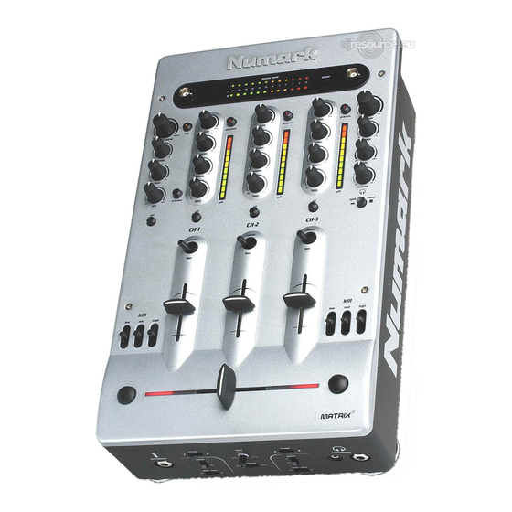
- Page 1 Matrix 3 Operating Instructions...
-
Page 2: Safety Precautions
Thank you for buying this Numark product. Please read these operating instructions so you will know how to operate this equipment properly. After you have finished reading these instructions, keep them for future reference. WARNING: TO PREVENT FIRE OR SHOCK HAZARD, DO NOT EXPOSE THIS APPLIANCE TO RAIN OR MOISTURE. -
Page 3: Table Of Contents
CAUTION! TO PREVENT THE RISK OF ELECTRIC SHOCK, DO NOT REMOVE COVER (OR BACK). NO USER-SERVICEABLE PARTS INSIDE. REFER SERVICING TO QUALIFIED SERVICE PERSONNEL. IMPORTANT The lightning flash with arrowhead symbol, within an equilateral triangle, is intended to alert the user to the presence of un-insulated "dangerous voltage" within the product's enclosure that may be of sufficient magnitude to constitute a risk of electric shock to persons. -
Page 4: Handling And Care
HANDLING AND CARE Location Install the mixer in a well-ventilated location where it will not be exposed to high temperatures or humidity. Do not install the mixer in a location that is exposed to direct rays of the sun, or near stoves or radiators. -
Page 5: Setup Diagram
SETUP DIAGRAM Power the mixer before powering the amplifier. Turn off the amplifier before turning off the mixer. TO CH3 TO REC TO CH2 TO CH1 TO CH2 TO CH1 TO CH3 TO AMP SETUP DIAGRAM PAGE 4... -
Page 6: Controls
CONTROLS 1. Microphone Controls "Mic" (Microphone Trim) This knob adjusts the volume of the main microphone. When turned all the way to the left, the volume is at -8dB. When turned to the right, the volume is at 0dB. The Microphone Trim should be set at -8dB when connecting and disconnecting a microphone from the Quarter-Inch "Microphone"... - Page 7 SECTION 1 MICROPHONE CONTROLS PAGE 6...
- Page 8 CONTROLS 2. Primary Mixing Input Controls for CH-1 to CH-3 "Gain" (Input Level Trim) This rotary control adjusts the input signal levels of the inputs. Turning the knob completely to the right (clockwise) increases the level to +8dB. Turning the knob completely to the left (counter clockwise) decreases the level to -8dB.
- Page 9 SECTION 2 PRIMARY MIXING INPUT CONTROLS PAGE 8...
-
Page 10: Meters And Lighting
CONTROLS 3. Meters and Lighting "Master Level" (Master Level Meter) This meter displays the stereo output levels of the master signal. The display ranges from -40dB to +10dB. Dual BNC Style Light Connectors Two BNC style lights can be connected simultaneously to these 12V receptacles. 4. - Page 11 SECTION 3 SECTION 4 METERS+ LIGHTING, CUEING CONTROLS PAGE 10...
-
Page 12: Master Output Controls
CONTROLS 5. Master Output Controls "Master" (Main Output Level Control) This rotary control adjusts the main output levels for any equipment connected to the Master Output on the rear panel (Section 9 "Inputs and Outputs"). Turning the knob completely to the right increases the level to +10dB and turning the knob completely to the left mutes the signal. - Page 13 SECTION 5 SECTION 6 MASTER OUTPUT, CROSSFADER CONTROLS PAGE 12...
-
Page 14: Special Crossfader Related Controls
CONTROLS 7. Special Crossfader Related Features "Kill" (Flash/Eliminate EQ Toggles) These toggles eliminate the signal level for their respective frequency (low range, midrange and high.) In the upward position, the switch will lock in position. In the downward position, the switch eliminates the frequency until it is released. - Page 15 SECTION 8 SECTION 7 SPECIAL CROSSFADER RELATED FEATURES, EFFECTS PAGE 14...
-
Page 16: Inputs And Outputs
CONTROLS 9. Inputs and Outputs CH-1, CH-2 and CH-3 Phono/Line Stereo Inputs Each channel has a selectable phono level input (phonograph level/line level) and a line level input. The line level input is used to connect CD players and other line level devices. When connecting a turntable to the phono input, the switch must be set to "PHONO"... - Page 17 "Balance Output" (Balanced Quarter Inch Stereo Output) These Quarter Inch outputs are for sending a balanced level signal to a PA system or recording device. The level of the balanced output signal will also increase with the "master" volume control. These outputs are durable and offer a better output signal than the "master"...
-
Page 18: Customizing And Servicing Your Mixer
CONTROLS 10. Customizing and Servicing Your Mixer Replacing the Crossfader This mixer features a replaceable Crossfader. The Crossfader can be removed from the mixer by loosening the two screws at the endpoints of the fader (See illustrations at right.) Follow the steps below for removing the top panel to have access to the Crossfader. Customizing the Direction of the Input Selector Switches This mixer features multi directional Input Switches that can be removed and rotated to one of eight positions (See illustrations at right.) Each Input Selector Switch is secured to the mixer by two adjacent... - Page 19 Replacing the Crossfader 1. After removing the top panel, remove the two screws that secure the crossfader using a #2 Philips Screwdriver. Customizing the Direction of the Input Selector Switches 1. After removing the top panel, remove the two screws that secure the selector switch you want to rotate using a #2 Philips Screwdriver.
-
Page 20: Specifications
SPECIFICATIONS Inputs: Line: 10K ohm input impedance 80mV rms sensitivity for 1.22V output Mic: 600 ohm input impedance unbalanced 0.85mV rms sensitivity for 1.22V output 57mV rms max input Phono: 47Kohm input impedance 1.3mV rms sensitivity @ 1KHz for 1.22V output Outputs: Line: 9V rms max... -
Page 21: Limited Product Warranty
NUMARK dealer and continuing for the following period of time after that date for (2) Years. The warranty is extended to (3) Years with the completion of the warranty card provided that the warranty card is completed and returned within (30) days from the date of purchase. - Page 22 Matrix 3 Manual /English Copyright Numark Industries, LLC 2001...
Need help?
Do you have a question about the MATRIX3 and is the answer not in the manual?
Questions and answers