Table of Contents
Advertisement
Quick Links
Advertisement
Table of Contents

Related Manuals for Mikrotron CAMMC134 Series


Summary of Contents for Mikrotron CAMMC134 Series
- Page 1 CAMMC134x Camera Reference Guide V 2.0...
-
Page 2: Table Of Contents
Memory Pointer/Counter Register :R2 ..................21 Memory Read Register :R3[31...30] = 0 ..................22 ExposureTime Register :R3[31...30] = 4 ..................23 FrameRate Register :R3[31...30] = 8 ................... 24 Read Single Memory Registers ....................24 Read All Analog Registers......................25 page 2 of 54 MIKROTRON GmbH... - Page 3 Cleaning the IR-filter ......................... 47 Changing the Battery ........................47 Technical Data ........................... 48 Pin Assignments......................... 49 Power Connector ..........................49 Trigger Connector ..........................49 Spectral Response of CAMMC134x ..................... 50 Dimensions ..........................52 MIKROTRON GmbH page 3 of 54...
-
Page 4: About This Reference Guide
Although this description has been produced with care, it can neither be complete nor be free of errors. MIKROTRON GmbH cannot be held legally responsible for any errors or missing information in this description. In case problems occur, please contact our service team: Email: info@mikrotron.de... -
Page 5: Warranty And Non-Warranty Clause
+49 - 89 - 7263 4250 or by email: info@mikrotron.de Write down the camera type and serial no. and send the camera back to your distributor. If no distributor is available, send it back to MIKROTRON ( page 54). MIKROTRON GmbH page 5 of 54... -
Page 6: Conformity And Use Of The Product
制造说明: 此设备的生产与测试依照FCC条例第15条条例,符合A类电子设备标准。产品提供在商用使用环境 中的合理保护,以防止使用过程中可能涉及到的损害。 此设备会产生、使用并可发射出无线电波,如果未按照本手册中所述安装和使用,可能会对无线 通信设备产生干扰。如本设备在居民区操作出现干扰等情况,用户需要自费处理。 备注:请注意,如未按照此使用说明操作而自行更改设备,那么您将无权使用本设备。 規制適合宣言とご使用について (米国FCC) この機器は、FCC規則のパート15に定められたクラスAデジタル装置に関する規制要件に 基づいて所定の試験が実施され、その適合が認証されています。 これらの規制要件は、商 業環境において機器を使用する際、有害な干渉に対する妥当な保護を提供するために設けら れています。 この機器は、無線周波数エネルギーを生成かつ利用するとともに、放射する こともあります。 このリファレンスガイドの指示に従って設置および使用が行われない場 合は、無線通信に有害な干渉を引き起こす恐れがあります。 この機器を住宅地で利用する と有害な干渉を起こすこともあり、その場合、使用者は自己負担において適切な対策を講じ る必要があります。 注意事項: このリファレンスガイドに明示的に承認していない変更や修正を行った場合 には、本製品を使用する権利が無効となることがあります。 page 6 of 54 MIKROTRON GmbH... -
Page 7: Supplements
MIKROTRON customers using or selling these products for use in such applications do so at their own risk and agree to fully indemnify MIKROTRON for any damages resulting from such improper use or sale. -
Page 8: Eu Declaration Of Conformity
Information technology equipment - Radio disturbance characteristics - EN 55022:2006 + A1:2007 Limits and methods of measurement Einrichtungen der Informationstechnik – Funkstöreigenschaften - Grenzwerte und Messverfahren Unterschleissheim, May 6, 2015 Dipl.-Kfm. Christian Pilzer Unterschleißheim, den 06.05.2015 page 8 of 54 MIKROTRON GmbH... -
Page 9: Hardware
Scope of Delivery Please check whether the delivery is complete, before you start to install the camera: Camera CAMMC134x (Cube4) C-Mount Lens Mikrotron Support CD 1 power supply 12 VDC; 1.25A min. 1 power cable MIKROTRON GmbH... -
Page 10: Identification Plate
100g; vibration: 10g at 5 to 2500 Hz ImageBLITZ option IRIG-B input processing option M6/M11/M13 extended buffer size multi sequence mode power on recording standby Voltage: allowed voltage DC 10.5 – 30 V page 10 of 54 MIKROTRON GmbH... -
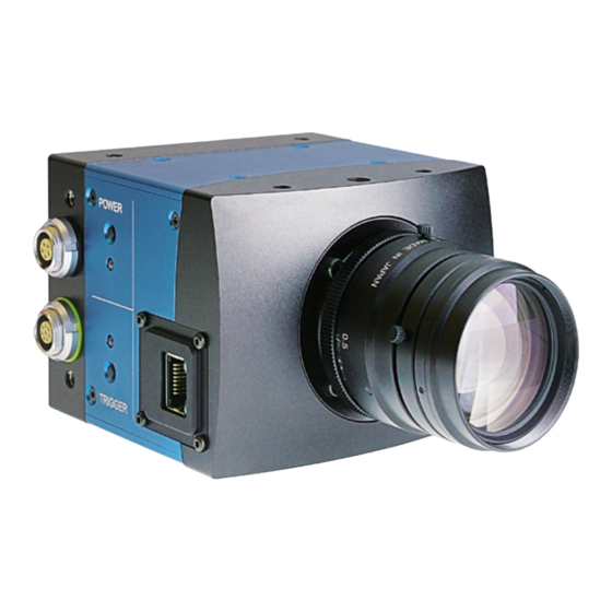
Page 11: Interfaces And Buttons
Figure 2: Buttons and LEDs of the camera Remark: For more information about the pinning of the power and trigger connector page 49. MIKROTRON GmbH page 11 of 54... - Page 12 The internal NiMh battery has a capacity of 2.2 Ah and is charged automatically within three to four hours if an external power supply is available. If the camera is operating and external power is applied, the battery will be charged. power LED camera status page 12 of 54 MIKROTRON GmbH...
-
Page 13: Power Supply
Instead, contact our service team and ask for a RMA number info@mikrotron.de and send the camera back to MIKROTRON. Damages caused by battery change are not covered by warranty. Although each camera comes with a power supply, the power connector pinning of the 5-pin Lemosa might be helpful e.g. -
Page 14: Standby Mode
If a CAMMC134x camera is in standby mode, the Status LED will be OFF and the Power LED will be flashing. Remark: A camera in standby mode has to be connected with the power supply before waking it up. page 14 of 54 MIKROTRON GmbH... -
Page 15: Installation Of The Camera
Remark: Normally, an IP address will be assigned automatically. This may take a few minutes. In case you want to accelerate this process or in order to assign a certain IP address (page 18). MIKROTRON GmbH page 15 of 54... -
Page 16: Connecting External Signals
ARM signal. If Sync out is selected, this output will carry a strobe that corresponds to the selected exposure time of the camera. If ARM is selected, it will be active when the camera runs in Ring Mode and is recording. page 16 of 54 MIKROTRON GmbH... -
Page 17: Sync Out / Arm Output Signal Definition
The output polarity is positive when the selected signal is active. The suppressor diode protects the output against reverse voltages. It starts conducting if the voltage at the output pin is greater 6V. MIKROTRON GmbH page 17 of 54... -
Page 18: Configuration
Even if continuous writing is selected (:R1[1] = 1), this bit can be cleared at any time by stopping writing on an expired write or trailer counter. If single writing is selected, writing to an expired write or trailer counter will automatically be stopped. page 18 of 54 MIKROTRON GmbH... -
Page 19: Memory Registers
0x1FFFFFFF. A memory board provides 2 GByte. CAMMC134x cameras can be equipped with two memory boards providing 4 GBytes altogether (see also command for camera identifier and memory size). Use the capital letter :R in order to program the memory register. MIKROTRON GmbH page 19 of 54... -
Page 20: Memory Write Register :R1
:V and should be set to the same value as read with :z1 after power up of the camera. Please pay attention: the bits in :R1 are not the same as in :V response! bit 4 can be cleared/set if a reset of memory control logic is required. page 20 of 54 MIKROTRON GmbH... -
Page 21: Memory Pointer/Counter Register :R2
Bits Value Description :R2<ixxxxxxx> 31...30 WriteBaseAddress register [8words] i = 0, 4, 8, 0xc ReadBaseAddress register [8words] xxxxxxx = 7 ASCII hex characters WriteLength register [8words] ReadLength register [8words] 29...0 0x3fffffff..5 Write/Read address/length [8words] MIKROTRON GmbH page 21 of 54... -
Page 22: Memory Read Register :R3[31
:R1-command or by applying an external trigger. Register 3 can be read at any time with the :z6 command. It will return its content in 8 ASCII characters. page 22 of 54 MIKROTRON GmbH... -
Page 23: Exposuretime Register :R3[31
ExposureTime = 126.51 ms Note: ExposureTime setting is limited by the time for one frame, which is set with FrameRate register. ExposureTimes, which are longer than one frame, will be reduced to the duration of one frame. MIKROTRON GmbH page 23 of 54... -
Page 24: Framerate Register :R3[31
:R30, bit 0 might be clear thru previous stop read action read :R34 (not yet supported) read :R38 Note: Result of command :z4 and :z5 will change with repeated readings if memory read/write is in progress. page 24 of 54 MIKROTRON GmbH... -
Page 25: Read All Analog Registers
FPGA - register <xxx> =0…3ff #005433A read serial number (#), part of identifier, 11-B2.03- microcontroller-version (V..) and V0.82- FPGA - version (F..). F1.71 camera read actual PowerUpProfile, data output in hex profile: MIKROTRON GmbH page 25 of 54... -
Page 26: Sensor Registers
0x3ff recording while trigger is active :r3<xxx> 9..0 0..0x3ff number of lines + 1 :r4<xxx> 9..0 0..0x4f address of first pixel of a line :r5<xxx> 9..0 0..0x4f address of last pixel of a line page 26 of 54 MIKROTRON GmbH... - Page 27 ImageBLITZ top/bottom line zebra striped indicator in the frames :rb<xxx> 9..0 0...0x3ff release condition 10 is :ra[8] :rc<xxx> 9...0 0...0x3ff ImageBLITZ top line address :rd<xxx> 9...0 0...0x3ff ImageBLITZ bottom line address :re<xxx> 9...0 0...0x3ff write ImageInformationField MIKROTRON GmbH page 27 of 54...
-
Page 28: Image Quality
PIXVDD is the supply voltage of the analog stage of each pixel inside the sensor. This parameter is important for the image quality. The factory adjustment is recommended to use. Command: :a4<x > <x > : range, typ. 32h ..40h Response: none or ACK (if enabled) page 28 of 54 MIKROTRON GmbH... -
Page 29: Image Size And Position
Address of the First Line Register r1 defines the first line to be displayed. Command: :r1<x > <x > ..Range 000h ..3fdh Response: none Example: :r1100 100h = image starts at line 257 MIKROTRON GmbH page 29 of 54... - Page 30 > ..Range 000h ..04fh Response: none Calculation of the value of r5: Value of r5 = Pixel no./16 Note: The difference r5 - r4 has to be in the range of 0 r5-r4 4fh. page 30 of 54 MIKROTRON GmbH...
-
Page 31: Clock Selection
5. Set sensor controller to new image size (:r1,:r2, :r3, :r4, :r5) 6. Enable sensor controller (:r6[4]=1) and wait for 1/fps to insure that there are output correct images 7. Enable (if necessary) the memory controller to desired action. MIKROTRON GmbH page 31 of 54... -
Page 32: Image Speed
Use Pin 8 of the I/O connector as input. Synchronization is enabled with register :rf[0] = 1. Use only with synchronous exposure (:r6[7...4]=3). page 32 of 54 MIKROTRON GmbH... -
Page 33: Imageblitz Trigger
Out of the 10-bits sensor data either the most significant 8 bits (gain 1), or bits 8...1 (gain 2), or the least significant 8 bits (gain 4) are selected. Command: :r700x x = 0: gain 1 x = 4: gain 2 x = 8: gain 4 MIKROTRON GmbH page 33 of 54... -
Page 34: Test Image
Note: Issue this command only, if the PowerUpProfile was successfully tested. Load Camera PowerUpProfile Loads the PowerUpProfile to the camera profile and adjusts all camera settings according to the settings in the PowerUpProfile. Command: page 34 of 54 MIKROTRON GmbH... -
Page 35: Read Serial Number, Firmware Revision And Model
(carriage return and line feed) Serial number Firmware versions Camera identifier Firmware versions e.g.: B2.03 ..bootloader program version of microcontroller V1.01 ..application program version of microcontroller F1.85 ..sensor FPGA program version MIKROTRON GmbH page 35 of 54... - Page 36 0080 reserved 0100 achievement 0 = HG (high G) 1 = standard 0200 company version 0 = Weinberger 1 = Mikrotron 11,10 0C00 camera type 00 = MC133x 01 = MC253x 10 = MC134x 11 = not defined 1000 multi-sequence feature (MS)
-
Page 37: Read Extended Camera Identifier
monochrome camera 2 GByte memory standard (not HI-G) Mikrotron MotionBLITZ Cube4 (CAMMC134x) Multi sequence and ImageBlitz installed Memory made of 1Gbyte Rams Extended + Base Camera Identifier description, all digits in hexadecimal notation: 8+2+1 = B... -
Page 38: Read Camera Settings
1 * 4 bytes (high byte first) reserved register Output the camera settings as ASCII string Format: 8 * (1 * CR + 32 ASCII-chars) plus 1 * CR at the end, i.e. 265 Bytes in total page 38 of 54 MIKROTRON GmbH... -
Page 39: Image Information Field
Command: :i<n><16char.text> ; write free text n = text line number Command: :I<n> ; read free text n = text line number MIKROTRON GmbH page 39 of 54... -
Page 40: Irig-B
This is achieved by reading the actual content of the port A with the command “:?par”, setting the bit 7 in the read string and resending this to the camera with the “:?paw” command. page 40 of 54 MIKROTRON GmbH... - Page 41 / orange constant flashing external green flashing 1 ... 5 times internal (battery) If the battery is fully charged, there is a every 2 seconds quintuple blinking. If the battery gets empty, there is a single blinking. MIKROTRON GmbH page 41 of 54...
-
Page 42: Firmware
CAMMC134x’s logic is integrated into two FPGAs (Field Programmable Gate Array), which’s configuration is stored in an EEPROM. Upon power up or a command the FPGA is loaded with this configuration. Configuration data can be downloaded via the Gigabit Ethernet interface. Mikrotron may provide configuration files (*.ibf) on request. -
Page 43: Assigning An Ip Address
Use the shielded Gbit Ethernet cable. 2. Open »Network and Sharing Center« in the Windows Control Panel and open your LAN connection 3. Click [Properties] The properties dialog for the connection will be displayed. MIKROTRON GmbH page 43 of 54... - Page 44 Assigning an IP Address Cube4 – CAMMC134x Camera 4. Highlight Internet Protocol Version 4 (TCP/IPv4) 5. Click [Configure] 6. Assign a valid IP address that is currently not in use, e.g. IP:192.168.110.1, Subnet-mask: 255.255.255.0 7. Click [OK] page 44 of 54 MIKROTRON GmbH...
-
Page 45: Working With Several Network Cards
IP address of the next network card Proceed for each card as described on page 17 and make sure that the subnet mask for each card is the same. MIKROTRON GmbH page 45 of 54... -
Page 46: Mount An F-Mount Adapter
1. Loose the 4 torx screws at the camera front housing 4 torx screws (M3) adjustable distance ring Remark: Please, take care that neither the IR-filter of a color camera nor the plating of the inner f-mount cylinder will be damaged. page 46 of 54 MIKROTRON GmbH... -
Page 47: Maintenance
The battery of CAMMC134x cameras is equipped with an additional fuse and a temperature probe. Therefore, never change the battery yourself! Instead, contact our service team and ask for a RMA number (info@mikrotron.de) and send the CAMMC134x camera back to MIKROTRON... -
Page 48: Technical Data
Shock & vibration 100g, 10grms Dimensions (WxHxD) 93 x 69 x 92 mm (c-mount) 93 x 69 x 128 mm (f-mount) Case temperature +5 ..+45° C Weight ca. 900 g Lens mount C-mount or F-mount page 48 of 54 MIKROTRON GmbH... -
Page 49: Pin Assignments
*) IRIG-B input: The level of the IRIG-B signal connected at pin no. 6 should be typically 3V for ‚mark’, 1V for ‚space’. Important is the ratio of the signal level of mark and space of 3 to 1. MIKROTRON GmbH page 49 of 54... -
Page 50: Spectral Response Of Cammc134X
12 x 12 µm Active area 15.36 (H) x 12.29 (V) mm Fill factor 40 % Light sensitivity 1.6 V/lux-sec @ 550 nm Dynamic range up to 59 dB with multiple slope Full well charge 63000eˉ page 50 of 54 MIKROTRON GmbH... - Page 51 Spectral Response of CAMMC134x Cube4 – CAMMC134x Camera MIKROTRON GmbH page 51 of 54...
-
Page 52: Dimensions
C-Mount but without lens. To fasten the camera there are two mounting holes M 4x7 mm and one tripod connection on each side available. Remark: Maximum torque for M4 fastening screws: 2.5 Nm C-Mount F-Mount page 52 of 54 MIKROTRON GmbH... - Page 53 W h i t w o r t h 1 / 4 " ( 3 x ) W h i t w o r t h 1 / 4 " ( 3 x ) MIKROTRON GmbH page 53 of 54...
- Page 54 Dimensions Cube4 – CAMMC134x Camera CAMMC134x Reference Guide Copyright © 2018 Mikrotron GmbH This version has been produced on 26 of October 2018 by MIKROTRON GmbH Landshuter Str. 20-22 85716 Unterschleissheim / Germany Phone: 0049 (0)89 7263420 www.mikrotron.de info@mikrotron.de...
Need help?
Do you have a question about the CAMMC134 Series and is the answer not in the manual?
Questions and answers