Sign In
Upload
Download
Table of Contents
Contents
Add to my manuals
Delete from my manuals
Share
URL of this page:
HTML Link:
Bookmark this page
Add
Manual will be automatically added to "My Manuals"
Print this page
×
Bookmark added
×
Added to my manuals
Manuals
Brands
Mikrotron Manuals
Digital Camera
MC4083
Reference manual
Mikrotron MC4083 Reference Manual
Hide thumbs
1
Table Of Contents
2
3
4
5
6
7
8
9
10
11
12
13
14
15
16
17
18
19
20
21
22
23
24
25
26
27
28
29
30
31
32
33
34
35
36
37
38
39
40
41
42
43
44
45
46
47
48
49
50
51
52
53
54
55
56
57
58
59
60
61
62
63
64
65
66
67
68
69
70
page
of
70
Go
/
70
Contents
Table of Contents
Bookmarks
Table of Contents
Table of Contents
About this Reference Guide
Remarks, Notes and Warnings
Registered Trademarks
Conformity and Use
Supplements
Declaration of Conformity
Warranty and Non-Warranty Clause
Scope of Delivery
System Requirements
Introduction
Most Important Features
Hardware
Rear Side of the Camera with DIN Connector
Rear Side of the Camera with 5W5 Connector
Connecting a Frame Grabber
DIN Connector
5W5 Connector
Connecting an External Power Supply
12 Pin Hirose Connector and I/O Signals
Pin Hirose and I/O Signals
Status LED
Resolution and Speed
Cleaning the Sensor or the Lens
First Steps
Initial Setup
Serial Number and Firmware
Powering-Up the Camera
Configure Your 4CXP Camera
Genicam Standard
Camera Registers
Bootstrap Registers
Standard
Revision
Xmlmanifestsize
Xmlmanifestselector
Xmlversion[Xmlmanifestselector]
Xmlschemeversion[Xmlmanifestselector]
Xmlurladdress [Xmlmanifestselector]
Iidc2Address
Devicevendorname
Devicemodelname
Devicemanufacturerinfo
Deviceversion
Deviceserialnumber
Deviceuserid
Manufacturer-Specific Addresses
Connectionreset
Deviceconnectionid
Masterhostconnectionid
Controlpacketsizemax
Streampacketsizemax
Connectionconfig
Connectionconfigdefault
Testmode
Testerrorcountselector
Testerrorcount[Testerrorcountselector]
Testpacketcounttx[Testerrorcountselector]
Testpacketcountrx[Testerrorcountselector]
Hsupconnection
Acquisition Control
Acquisitionmode
Acquisitionstart
Acquisitionstop
Acquisitionburstframecount
Triggerselector
Triggermode [Triggerselector]
Triggersource [Triggerselector]
Triggeractivation [Triggerselector]
Triggersoftware
Exposuremode
Exposuretime
Exposuretimemax
Acquisitionframerate
Acquisitionframeratemax
Testimageselector
Device Control
Devicereset
Image Format Control
Regionselector
Regionmode
Regiondestination
Width
Height
Decimationhorizontal
Decimationvertical
Offsetx
Offsety
Sensorwidth
Sensorheight
Widthmax
Heightmax
Pixelformat
Tapgeometry
Image1Streamid
Devicescantype
User Set Control
Usersetselector
Usersetload[Usersetselector]
Usersetsave[Usersetselector]
Usersetdefaultselector
Analog Control
Blacklevel
Gain
Gamma Correction
Custom Features
Txlogicalconnectionreset
Prstenable
Pulsedrainenable
Deviceinformationselector
Deviceinformation[Deviceinfoselector]
Fixedpatternnoisereduction
Customsensorclkenable
Customsensorclk
Analogregistersetselector
Analogregisterselector
Analogvalue
Infofieldframecounterenable
Infofieldtimestampenable
Infofieldroienable
Firmware and Update
Firmware Updater
Technical Data
Sensor
Camera
Spectral Response
MC4086 (Monochrome)
MC4087 (Color)
Bayer Color Filter
Bayer Pattern
Dimensions of MC4086/4087
Rear View
Side View
Dimensions of MC4082/MC4083
Rear View
Side View
Index
4CXP Camera Reference Guide V2.2
Advertisement
Quick Links
1
Most Important Features
2
4Cxp Camera Reference Guide V2.2
Download this manual
Remarks, Notes and Warnings
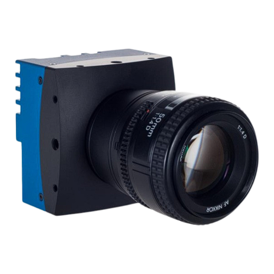
4CXP Camera
EoSens 4CXP
Reference Guide
page 1 of 70
MIKROTRON GmbH
Table of
Contents
Previous
Page
Next
Page
1
2
3
4
5
Advertisement
Table of Contents
Need help?
Do you have a question about the MC4083 and is the answer not in the manual?
Ask a question
Questions and answers
Related Manuals for Mikrotron MC4083
Digital Camera Mikrotron MC13xx User Manual
Mc13 series high speed cmos camera (53 pages)
Digital Camera Mikrotron MC130x User Manual
(68 pages)
Digital Camera Mikrotron MC136 Series Reference Manual
Genicam highspeed memory camera with gigevision interface (34 pages)
Digital Camera Mikrotron EoSens CL Series Manual
Highsensitivity highspeed cmos camera (43 pages)
Digital Camera Mikrotron MC1362 Manual
Highsensitivity highspeed cmos camera (43 pages)
Digital Camera Mikrotron CoaxPress MC258 Series Manual
(46 pages)
Digital Camera Mikrotron MC133x User Manual
High speed cmos camera (42 pages)
Digital Camera Mikrotron EoSens 4CXP Reference Manual
(70 pages)
Digital Camera Mikrotron EOSENS CL User Manual
High speed cmos camera • high sensitivity (51 pages)
Digital Camera Mikrotron eosens TS3 User Manual
(120 pages)
Digital Camera Mikrotron EoSens 3CL Manual
(43 pages)
Digital Camera Mikrotron EoSens 12CXP+ Reference Manual
(88 pages)
Digital Camera Mikrotron EoSens 3CXP Reference Manual
(63 pages)
Digital Camera Mikrotron MotionBLITZ Cube1 M3 Instruction Manual
Digital motion analysis recorder (85 pages)
Digital Camera Mikrotron EoSens 3CL User Manual
(40 pages)
Digital Camera Mikrotron CAMMC134 Series Reference Manual
(54 pages)
This manual is also suitable for:
Mc4086
Mc4087
Mc4082
Eosens 4cxp
Eosens 25cxp
Table of Contents
Print
Rename the bookmark
Delete bookmark?
Delete from my manuals?
Login
Sign In
OR
Sign in with Facebook
Sign in with Google
Upload manual
Upload from disk
Upload from URL


Need help?
Do you have a question about the MC4083 and is the answer not in the manual?
Questions and answers