Table of Contents
Advertisement
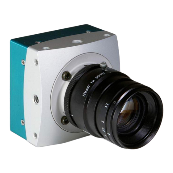
EoSens CL Camera Manual
HighSensitivity HighSpeed CMOS Camera
EoSens CL Camera Manual
Camera-Firmware:
Camera ID:
Copyright © 2008 Mikrotron GmbH
Mikrotron GmbH
Landshuter Str. 20-22
D-85716 Unterschleissheim
Germany
Rev. 1.04
B2.02-V1.04-F1.04
MC1360-63
Tel.: +49 89 726342 00
Fax: +49 89 726342 99
info@mikrotron.de
www.mikrotron.de
Advertisement
Table of Contents


Need help?
Do you have a question about the EoSens CL Series and is the answer not in the manual?
Questions and answers