Table of Contents
Advertisement
Quick Links
Advertisement
Table of Contents

Related Manuals for Anyload 805TS


Summary of Contents for Anyload 805TS
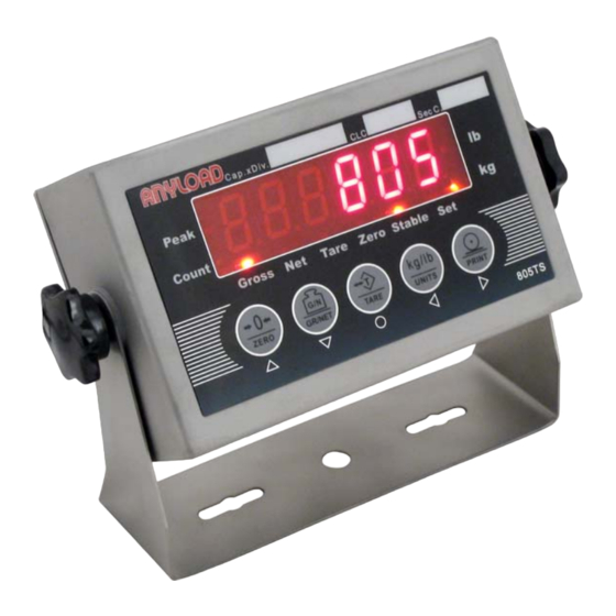
- Page 1 805TS INDICATOR MANUAL www.load-cell.com...
-
Page 2: Table Of Contents
1. Introduction ......................1 1.1 Operation Modes ..................1 1.2 Front Panel Keypad ...................2 1.3 Indicating Lights ..................2 1.4 Start Up.......................3 1.5 Operations....................3 1.5.1 Normal Weighing Mode..............3 1.5.1.1 Gross/Net Mode ..............3 1.5.1.2 Units ..................3 1.5.1.3 Zero Scale ................3 1.5.1.4 Acquire Tare................4 1.5.1.5 Remove Stored Tare Value ...........4 1.5.1.6 Print ..................4 1.5.2 Peak Mode Operations ..............4 1.5.2.1 Units ..................4... - Page 3 9.1 Error Messages ..................39 9.2 Software Version and Default Configuration Parameters ....40 9.2.1 Find out indicator software version ..........40 9.2.2 Restore Factory Setup Parameters (Default Configuration Parameters).....................41 9.3 Technical Specifications .................41 9.4 ASCII Codes Table ...................43 9.5 805TS Display Characters ...............44...
-
Page 4: Introduction
This manual provides installation, operation and configuration information of indicator model 805TS. It is recommended to go through the manual in details before installing, operating or configuring the indicator. When it is required to work inside the indicator enclosure for some procedures described, the work can only be performed by qualified technical personnel. -
Page 5: Front Panel Keypad
Most of the operation data setting including parameters setting and weighing range calibration are to be carried out in Configuration mode. Remove the back panel of indicator (refer to Fig 2-1 Sockets on Circuit Board). Switch on K1 jumper located at the lower corner. Indicator is in Configuration mode and display shows “F1”. -
Page 6: Start Up
“Zero”—— Light is on when load is within zero range (<1/4d). “Tare”—— Light is on when Tare setting is not zero. 1.4 Start Up Connect power supply. Indicator goes through a self checking process (showing all 0 to all 9, decimal point and indicator lights). -
Page 7: Acquire Tare
1.5.1.4 Acquire Tare When no Tare is stored (“Tare” light is off), place the container on the scale and wait until the “Stable” light is on. Press 【TARE】. Tare weight is stored. Display shows Net weight while “Net” light is on (refer to F6.1 Menu). 1.5.1.5 Remove Stored Tare Value When a tare weight is stored (“Tare”... -
Page 8: Zero Scale
1.5.2.4 Zero Scale When Peak mode is on (“Set” light is on), press 【GR/NET】 to switch indicator to Normal Weighing mode (“Set” light is off). Remove the load and when the “Stable” light is on, press 【ZERO】. Display shows zero value. -
Page 9: Remove Stored Tare Value
1.5.3.5 Remove Stored Tare Value When a tare value is stored (“Tare” light is on), press 【TARE】 and the stored tare value is removed. Display shows Gross weight and the “Gross” light is on (refer F6.1 Menu). 1.5.3.6 Input Item Code When in Count mode, press 【PRINT】... -
Page 10: Print
Note: During the process (2), (3) and (4) above, turn on the K1 switch to cancel the Count Items Average Weight Setup and return to the Weighing mode. 1.5.3.8 Print When in Count mode (display shows “nxxxxx”), place the items which are to be counted onto the scale. -
Page 11: Kout : Relay Signal Outputs
2.3 KOUT : Relay signal outputs Fig. 2-2 Relay Connection ports 2.4 K3 : Output:RS485/RS232 Selectable output by switch K3:RS485/RS232 2.5 Load Cell Input 1(V-) —— Excitation- 2(VS-)—— Sense- 3(IN+)—— Signal+ 4(GND)—— Signal ground 5(IN–)—— Signal- 6(VS+)—— Sense+ 7(V+)—— Excitation+ 2.6 COMM : Serial Communication port (see Fig. -
Page 12: Front Panel Configuration
Configuration mode. 3.1 Front Panel Configuration When configuring, keypad functions as shown in Fig. 3-1. Table 3-1 Basic functions of Level 1 Submenu Menu Menu Function Config Configure grads, zero tracking, zero range, motion band, overload, sample rate, digital filtering and zero scale. See Section 3.2.1. Format Set decimal point location, display divisions, display rate and display unit. - Page 13 is editable values. Level Level Menu Menu 2nd Level 2nd Level Menu Menu Value Value Value Value Fig. 3-2 Menu Configuration Flow Diagram There are 4 directional keys to be used for configuration operation. , , , , are for horizontal movement in the same level menu and parameters. are for ,...
-
Page 14: F1(Configuration) Menu
3.2.1 F1(Configuration) Menu Fig. 3-4 F1 (Configuration) Menu Structure Table 3-2 F1(Configuration)Menu Parameters... - Page 15 F1(Configuration)Menu Parameter Choices Description Level 2 Submenu Graduations. Specifies the number of full scale F1.1 graduations. The value entered must be in the number (Grads) range 1-100 000. Graduation=Capacity/Display Divisions. Display divisions primary secondary units are specified in the F2 (Format) Menu.
- Page 16 F1.7 1√ higher the value, the lower is the effect acting upon (Digital Filter 1) the indicator due to noise and mechanical vibration and hence having a more accurate display. However, it slows down the settling rate of the indicator. F1.8 (Digital Filter 2)...
-
Page 17: F2(Format) Menu
3.2.2 F2(Format) Menu Fig. 3-5 F2 (Format) Menu Table 3-2 F2(Format) Menu F2(Format)Menu Parameter Choices Description Level 2 Submenu 0(lb) F2.1 Specifies the unit used of the Primary unit. (Primary Unit) 1(kg)√ 0(888888) Specifies the decimal position of the Primary unit. F2.2 Note: If F2.4=5, when on calibration step F3.2 to 1(88888.8)√... -
Page 18: F3(Calibration) Menu
0(888888)√ F2.4 Specifies the decimal position of the Assistant unit. (Assistant Unit When F6.1 is set to 0 or 2, the decimal position of Decimal Point the Assistant unit is defined by the decimal position location) of the Primary unit. 1(88888.8)... -
Page 19: F4(Serial) Menu
Parameter Choices Description Level 2 Submenu F3.1 Display and edit the zero calibration A/D count (WZero) — value. Do not adjust this value after F3.3 (WValue) has been set. Refer to Section 4. F3.2 Display and edit the test weight value, the value (WValue)... -
Page 20: F5(Mode) Menu
0(1200) Specifies settings for baud rate. F4.1 1(2400) (Baud) 2(4800) 3(9600)√ 0(8NONE)√ F4.2 Specifies settings for the number of data bits. (Bits) 1 (7EVEN) 2 (7ODD) 0(con) F4.3 Selects the mode of data transmission. 0(con) is (Mode) for continuous transmission and 1(comm) is for 1(comm)√... - Page 21 Config Format Serial Mode Relay PFormat Calibration F5.3 F5.4 F5.1 F5.2 F5.5 Sequence Zero Number Work mode (General) Press Enter Press Enter key to begin key to begin (Peaker) (Counter) 1000 Fig. 3-8 F5(Mode) Menu Table 3-5 F5(Mode) Menu F5(Mode)Menu Parameter Choices Description...
-
Page 22: F6(Relay) Menu
F5.3 — Sets the scale to zero before inputting the average (Zero) weight of counted items. Refer to Section 5. Specifies the quantity of sample counted items. Refer to Section 5. F5.4 (Sampling Quantity) 1000 F5.5 — Displays and edits the average weight of the (Average Weight)... -
Page 23: F7(Ver) Menu
F6.1 1 (OMIL) removal is only allowed when Gross = 0. When (mode) NONE is selected, Tare removal can be done at any 2 (CANADA) weighing mode. 3 (NONE) For NTEP and OIML, a new Tare can be acquired even when there is a stored Tare. For CANADA, a new Tare can be acquired after the stored Tare is removed. - Page 24 F7.1 Number Consecutive Numbering. Allows sequential (CONSNU) numbering for print operations. The consecutive number value is incremented following each print operation. The initial value of this parameter is set to the start up value specified on the CONSTU (F7.2 value). Refer to Section 7.4 F7.2 Number Consecutive Number Start Up Value.
-
Page 25: F8(Pformat) Menu
Fig. 3-11 F8(PFormat) Menu F8 (PFormat) Menu is used for setting Print format of serial print output. Refer to Section 7. 4. Calibration The calibration of 805TS consists of the following steps: Zero calibration Entering the test weight value Span calibration... - Page 26 Fig. 4-1 F3(Calibration) Menu The following section describes calibration procedure for each of the calibration methods: (1) Turn on the K1 switch to set indicator to the Configuration mode (display shows “F 1”) and remove all weight from the scale platform. If the test weights require hooks or chains, place the hooks or chains on the scale for zero calibration.
-
Page 27: Count Items Average Weight Setup
(6) F 3.4 Menu is used to remove a calibration offset when hooks or chains are used to hang the test weights. When display shows “F3.4”, there are 2 options : If no other apparatus is used to hang the test weights during calibration, remove the test weight and press to return to F4 Menu. - Page 28 Config Format Serial Mode Relay PFormat Calibration F5.3 F5.4 F5.1 F5.2 F5.5 Sequence Zero Number Work mode (General) Press Enter Press Enter key to begin key to begin (Peaker) (Counter) 1000 Fig. 5-1 Count Items Average Weight Setup Menu Setup procedure is as follow: (1)...
-
Page 29: Relay Output Setup
quantity. Press to go to the next menu. Display shows “F5.5”. (6) Press when display shows “F5.5”. Display shows “CAL” while processing the average weight setting. When complete, there are 2 possible outcomes : The average weight is too small and display shows “—E5—“. Press return to F5.5 Menu and display shows “F5.5”. - Page 30 (6) Turn off the K1 switch to exit from Calibration mode and enter into Weighing Mode. Config Format Serial Mode Relay PFormat Calibration F6.1 F6.2 F6.3 REGULA number number (NTEP) (OIML) (CANADA) (NONE) Fig. 6-1 Relay Output Menu Fig. 6-2 Relay Output-Upper and Lower Values...
-
Page 31: Print Format
Fig. 6-2 Relay Output-Upper and Lower Values Note 1 : Must ensure F6.3 (P2) value>F6.2(P1)value to give proper relay output Note 2: weight value is in net weight and is according to the unit in F2.1 setting (Refer to F2 Menu in Section 3.2.2). 7. -
Page 32: Gfmt And Nfmt Print Format Input
printed as text on the ticket. Text characters can include any ASCII character shown in Appendix 9-4. The maximum number of characters that can be input into each print format is 250. Table 7-1 Print Format Commands Command Description <G> Gross weight in displayed units. - Page 33 Config Format Serial Mode Relay PFormat Calibration F8.1 F8.2 F8.3 GFMT NFMT Default Press to insert a Press Enter to Same as GFMT space before the Load Default Format active character Display first 6 characters of Scroll right in format string format Scroll left in format string Increment ASCII value of...
-
Page 34: Default Formatting
When complete character editing, press to return to (4) above and to perform editing other characters. When finish editing, press to return to F8.1 and display shows “F8.1”. Press to go to F8.2 Menu and display shows “F8.2”. Refer to (3) to (6) for format editing of NFMT. -
Page 35: Date And Time Setting
Detailed Setup Procedure: Fig. 7-2 Consecutive Numbering Setup (1) Turn on the K1 switch to set indicator to the Configuration mode. Display shows “F1”. (2) Press until display shows “F7” (see Fig. 7-2). Press to go to F7.1 Menu. Display shows “F7.1” (3)... -
Page 36: Serial Communication
(6) Turn off the K1 switch to exit from Calibration mode and enter into Weighing Mode. 8. Serial Communication Indicator has the following two serial communication modes: Continuous transmission Transmission upon request (from an external PC) Set up Baud, Bits, Parity, Mode and Test in F4 Menu. Detailed Setup Procedure is as follow: Fig. -
Page 37: Transmission Upon Request
at 1. These parameters are suitable for continuous transmission and transmission upon request modes. Fig. 8-2 Format of Continuous Transmission 8.2 Transmission Upon Request Specify F4.4=1 as Section 8.1 above. After selecting the mode, indicator transmits data upon request according to Fig. 8-3 and Fig. 8-4. When receiving a command, indicator sends “OK”... - Page 38 Fig. 8-3 Transmission Format from PC Example : Set BLOCK to “G” (which is 47H) in ASCII code. Inspection and BCC calculation are as follow: ASCII “OR” with 30H...
-
Page 39: Communication Command
Respond Format from Indicator Fig. 8-4 Respond Format from Indicator 8.2.2 Communication Command 8.2.2.1 Transmit Current Weight Value Command data from PC<BLACK> Format: G (ASCII 71) Response data from indicator<BLACK> Format see Fig. 8-5... -
Page 40: Zero Scale
Fig. 8-5 Respond to<BLACK>data after receiving G command Example: PC receives data from indicator PC sends: 01H,31H,02H,47H , 03H,74H , , , , , , , , , Indicator responds:01H,31H,02H,20H , , 03H,3BH Data received in gross weight 1072kg。 8.2.2.2 Zero Scale PC command data <BLACK>... -
Page 41: Serial Communication Tests
Fig. 8-6 Print Format Command Transmission Sequence Note: When <G/N> is ‘G’ (ASCII 72), the format followed is the gross weight print mode (GFMT). When <G/N> is ‘N’ (ASCII 78), the format followed is the net weight print mode (NFMT). Refer to Section 7 regarding GFMT and NFMT. Indicator respond format: Correct transmission “OK”, Incorrect transmission “??”. -
Page 42: Appendix
and receives response data from A indicator. There are following possible outcomes: After B indicator sends command, A indicator gives no response and B display shows “EC”. B indicator receives error message and B display shows “Er”. B indicator receives proper data from A indicator, both displays show identical message. -
Page 43: Software Version And Default Configuration Parameters
– – E 1 – – Incorrect operating Check parameters parameters according to Section 3 – – E 2 – – A/D exchange error S Check hardware qualified personnel – – E 3 – – Data reading error Check hardware qualified personnel –... -
Page 44: Restore Factory Setup Parameters (Default Configuration Parameters)
Press until display shows “F 7” (see Fig. 9-1). Press to go to F7 Menu. Display shows “F 7.1”. Press twice until display shows “F 7.3”. When indicator shows “F 7.3”, press again, display shows the current software version “XX.XX”. Software version cannot be edited. Press to return to F7.3 Menu. - Page 45 range of scale initial signal -1~+9mV input signal sensitivity 0.2uV /d(minimum) 1.5uV/d(recommended) zero scale range ±1.9%FS、±100%FS selectable tare range 0 ~ +100%FS operating temperature -10 ~ 40 ℃ ℃ operating humidity (without dew) ≯ supply power source with transformer AC220V(–15%~ +10%) ,0.2A without transformer DC 6V~8.5V,1A relay current...
-
Page 46: Ascii Codes Table
9.4 ASCII Codes Table... -
Page 47: 805Ts Display Characters
9.5 805TS Display Characters...
Need help?
Do you have a question about the 805TS and is the answer not in the manual?
Questions and answers