Advertisement
Advertisement
Table of Contents

Related Manuals for Anyload J04SA-16


Summary of Contents for Anyload J04SA-16
- Page 1 J04SA-16 Junction Box Signal Trim TECHNICAL MANUAL Version 24A...
-
Page 2: Table Of Contents
J04SA-16 Technical Manual | V24A TABLE OF CONTENTS 1. Introduction...................... 2. Specification...................... 3. Dimensions......................4. Installation......................5. Trimming Procedure..................6. Troubleshooting..................... www.anyload.com... - Page 3 J04SA-16 Technical Manual | V24A I. ABOUT THIS MANUAL Thank you for choosing the Anyload J04SA-16 load cell junction box. This field technicians and engineers to better accommodate installation, safety, junction box has been designed with direct customer feedback from the properly in the application.
- Page 4 J04SA-16 Technical Manual | V24A Symbol Description Indicates a potentially hazardous WARNING! situation which may result in serious Indicates a potentially dangerous injury or death. procedure which may cause injury or death. Indicates a potentially wrong CAUTION! Indicates a potentially wrong procedure which may result in damage to device.
-
Page 5: Introduction
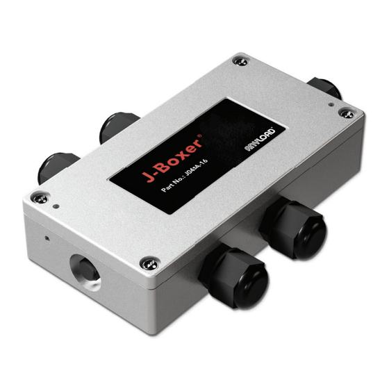
J04SA-16 Technical Manual | V24A 1. INTRODUCTION ANYLOAD J04SA-16 signal trim junction box is a versatile design . It also has a rubber sealing which seals the inside up to which connects four load cells together to give a single accurate and stable output. -
Page 6: Specification
J04SA-16 Technical Manual | V24A 2. SPECIFICATIONS Model J04SA-16 3.6 for 350Ω Signal Trim Trimming Trimming Range 6.3 for 700Ω 7.0 for 1000Ω Operating Temperature Range °C(° F) Max. Permissible Voltage °C(° F) Storage Temperature Range -10 TO +50 (+14 to +122) -
Page 7: Dimensions
J04SA-16 Technical Manual | V24A 3. DIMENSIONS www.anyload.com... -
Page 8: Installation
J04SA-16 Technical Manual | V24A 4. INSTALLATION Mechanical installation J04SA-16 junction box must be installed in a location that avoids access for servicing. Cutting the cable voids the warranty as it may interference from vibration or heat and it should be convenient to load cell. - Page 9 J04SA-16 Technical Manual | V24A Electrical Installation J04SA-16 junction box is used to connect four load cells together and then transfer a single output to an analogue input device such as an indicator. Analog Input Tank Weighing J04SA System Junction Box Insert the load cell cables through the plastic cable glands and page (pg.
- Page 10 Check the load cell color code listed in the data sheet as it depends the cable glands grips loose and tighten them securely after wiring. on the load cell manufacturer. 2. Strip the load cell cable wires. Anyload recommends stripping about 0.25” (6mm) for a solid connection. www.anyload.com...
- Page 11 J04SA-16 Technical Manual | V24A 3. Unscrew each pole using small flat screwdriver. Insert the wires and tighten them properly. 4. Connect the home run cable coming from the indicator following the same instructions as above. Find the color code of the indicator from the data sheet/manual of the indicator as it depends on the 5.
-
Page 12: Trimming Procedure
Anyload recommends letting the scale weighing system stabilize for about 10-15 minutes mechanically and electrically before performing the corner adjustment or any calibration with the indicator. - Page 13 J04SA-16 Technical Manual | V24A Trimming Method 1 Multi-Meter Pin 1 Multi-Meter Pin 2 1. Check the resistances of the potentiometers using a multimeter. the load cell terminal to confirm whether they match the factory Place one pin of the multimeter to Sig+ and one pin to Sig- of default settings.
- Page 14 J04SA-16 Technical Manual | V24A 2. Identify the potentiometers related to each load cell/section. It may be helpful to label them as corner 1, 2, 3, and 4 temporally to avoid any mix-up or confusion. 3. Place the appropriate test weight on the exact middle of the scale test weight capacity is dependent on the scale configuration, rules, and record the indicator reading.
- Page 15 J04SA-16 Technical Manual | V24A www.anyload.com...
- Page 16 J04SA-16 Technical Manual | V24A Trimming Method 2 1. Identify the potentiometer corresponding to each load cell/ section. It may be helpful to label them as corner 1, 2, 3, and 4 temporally to avoid any mix-up or confusion. 2. Turn all the potentiometers counterclockwise to keep the outputs at their minimum.
- Page 17 J04SA-16 Technical Manual | V24A 6. Follow the same process for other two corners. Check the zero balance after every adjustment as load cells are shunting interacting each other. 7. Test each load cell/sections again and repeat the steps 3, 4 and 5 as needed until get the required accuracy.
-
Page 18: Troubleshooting
Check the scale/weighing system mechanically to connections and properly tight them to avoid any loose avoid any touching/interactions. Check the indicator parameters setting such as filters. 4.3. Problem cannot be resolved: Contact Anyload customer support or your authorized dealer. www.anyload.com... - Page 19 J04SA-16 Technical Manual | V24A NOTES: www.anyload.com...
- Page 20 Web: www.anyload.com Anyload Weigh & Measure Inc. 6588 Antrim Avenue Burnaby, BC Canada V5J 4M5 Version 24A Content is subject to change without notice. Anyload is an 1SO 90001 certified company. © 2024 Anyload Weigh & Measure Inc. All rights reserved.
Need help?
Do you have a question about the J04SA-16 and is the answer not in the manual?
Questions and answers