
Related Manuals for Anyload 805TS Series


Summary of Contents for Anyload 805TS Series
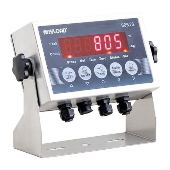
- Page 1 805TS 805BS Series & General Purpose Digital Weight Indicators Operations Manual (v1901) 805TS-B-17 805BS-B-17 805BS-TN-B (Lite Version)
-
Page 2: Table Of Contents
8.1 DC power supply 8.2 SW2 Switch 8.3 KOUT: Relay signal outputs 8.4 SW3: Output: RS485/COM 8.5 SW4: Output: USB/RS232 8.6 Load Cell Input 8.7 COMM: Serial Communication port 8.8 Printers ANYLOAD 805TS & 805BS Series Weighing Indicator Operations Manual (v1901) - Page 3 15.2 Software Version and Default Configuration Parameters 15.2.1 Find out the indicator’s software version 15.2.2 Restore to Factory Setup 15.3 Technical Specifications 15.4 ASCII Codes Table 15.5 Indicator Display Characters ANYLOAD 805TS & 805BS Series Weighing Indicator Operations Manual (v1901)
-
Page 4: Introduction And Product Features
Introduction and Product Features Thank you for choosing Anyload General Purpose Digital Weight Indicators. The 805TS and 805BS series indicators are general purpose indicators that provide high accuracy and reliability with multiple functions. These indicators have an A/D adopted conversion technology of a 24-bit resolution with a rate of conversion of up to 960 cycles per second and drives up to eight 350Ω... -
Page 5: Safety Recommendations
Before inserting the power adapter, the user must ensure that the operating voltage stated on the power adapter agrees with the mains voltage. If not, please contact Anyload Customer Service. ANYLOAD 805TS & 805BS Series Weighing Indicator Operations Manual (v1901) -
Page 6: Operation Modes
Remove the back panel of indicator (refer to Fig 8.1 Sockets on mainboard). Switch the jumper of SW2 to CFG setting. Indicator should be in Configurations mode and display will show “F1”. Refer to Section 9 for details. ANYLOAD 805TS & 805BS Series Weighing Indicator Operations Manual (v1901) -
Page 7: Front Panel Keypad
(refer to Section 9 for details). The signs/symbols can be used for inputting item codes during the Count Mode (refer to section 7.5 for details). ANYLOAD 805TS & 805BS Series Weighing Indicator Operations Manual (v1901) -
Page 8: Indicating Lights And Symbols
For the 805BS series, press the ON/OFF key at the front panel for 2 seconds to turn on the unit. Once on, the indicator will undergo a self- ANYLOAD 805TS & 805BS Series Weighing Indicator Operations Manual (v1901) -
Page 9: Operations
9.2 for menu operation flow diagram. Once F1 is displayed, press Arrow down key to enter F1.1. Press Arrow down key again, ‘00000’ will display. Press Arrow right or left key to move ANYLOAD 805TS & 805BS Series Weighing Indicator Operations Manual (v1901) -
Page 10: Enable Password Function
(will display P00000). This indicates that the password function is activated. Re-install the back panel and remember keeps the jumper of SW2 at CFG setting. ANYLOAD 805TS & 805BS Series Weighing Indicator Operations Manual (v1901) -
Page 11: Normal Weighing Mode
For the 805TS, the ”Gross” light is on when indicating gross weight and the ”Net” light is on when indicating net weight while the 805BS series the ”Gross” 10 | ANYLOAD 805TS & 805BS Series Weighing Indicator Operations Manual (v1901) -
Page 12: Units
805BS series, the unit symbol appears in the display like kg, lb or oz. 7.3.3 Zero Scale When in Gross mode (“Gross” light is on for 805TS series and “Gross” symbol is displaying for the 805BS series). Remove the load from scale and wait until the “Stable”... -
Page 13: Peak Mode Operations
F6.1 to 3 (F6.1=3 NONE) then set the parameter in F5.1 to 1 (F5.1=1) to activate the Peak mode. If F5.1=1, the “Peak” light will turn on (805TS series) or the “Peak” symbol will display (805BS series) then the indicator is in Peak mode (refer to F5.1 Menu setting). -
Page 14: Remove Peak Mode Value
When in Tare mode, Net weight is equal to Gross weight minus Tare weight. The “Gross” light is on (805TS series) or the “Gross” symbol is displaying (805BS series) when in Gross mode and the “Net” light is on (805TS series) or the “Net” symbol is displaying (805BS series) when in Net mode. -
Page 15: Units
7.5.5 Remove Stored Tare Value When a tare value is stored (for the 805TS series, the “Tare” light is on; for the 805BS series, the “Tare” symbol is displaying), press 【TARE】 to remove the stored value. -
Page 16: Printing In Count Mode
Fig. 4.1 (805TS series) and Fig.4.2 (805BS series). If the stored Item Code =00, the indicator goes to the Fast Setup of the Average Weight of the Counted Items (refer to Section 7.5.8). -
Page 17: Wire Installation
Note: When using a 4-wire load cell, move the two jumpers of SW1 to 4W. When using a 6-wire load cell, move the two jumpers of SW1 to 6W. 16 | ANYLOAD 805TS & 805BS Series Weighing Indicator Operations Manual (v1901) -
Page 18: Dc Power Supply
The SW4 jumper is to switch between USB and RS232 mode. When the jumper is moved to 232 setting, the serial output will be in RS232 standard, otherwise, the USB mode is activated. 17 | ANYLOAD 805TS & 805BS Series Weighing Indicator Operations Manual (v1901) -
Page 19: Load Cell Input
Set the jumper in SW2 to CFG. If the input is a 6-wire load cell, set the jumpers of SW1 to 6W, otherwise, set the jumpers to 4W Indicator should switch to Configuration mode and will display “F1” - the 18 | ANYLOAD 805TS & 805BS Series Weighing Indicator Operations Manual (v1901) -
Page 20: Front Panel Configurations
Set Relay operation modes. See Section 9.2.6 and Section 12. Indicate software version and regenerate default configuration parameters. See Section 9.2.7 and Appendix 15.2. PFormat Set print format. See Section 9.2.8 and Section 13. 19 | ANYLOAD 805TS & 805BS Series Weighing Indicator Operations Manual (v1901) -
Page 21: Menu Structure And Parameters Descriptions
Fig. 9.1.1 Keypad functions in Configuration Mode for 805BS series Fig. 9.1.2 Keypad functions in Configuration Mode for 805TS series 9.2 Menu Structure and Parameters Description Menu structure is shown in diagram below. In the actual Menu structure, the selected Menu item is displayed horizontally. In most Menus, setting parameters and parameter value are shown in tables. - Page 22 Fig 9.1.4, directional keys are used to edit the digit selected, and to increase or decrease the value of the selected digit. Editable Parameter 21 | ANYLOAD 805TS & 805BS Series Weighing Indicator Operations Manual (v1901)
-
Page 23: F1 Configuration Menu
9.2.1 F1 Configuration Menu Fig. 9.2.1.1 F1 (Configuration) Menu Structure 22 | ANYLOAD 805TS & 805BS Series Weighing Indicator Operations Manual (v1901) - Page 24 Some operations, 5(20D) including Zero, Tare and Print, 6(OFF) require the scale to be at standstill. When F1.4 is selected OFF, F1.2 should also be set to OFF. 23 | ANYLOAD 805TS & 805BS Series Weighing Indicator Operations Manual (v1901)
- Page 25 ) 805BS-TN-B the indicator to zero the scale and saves current zero for next powering up. Note: Parameters that are in check are the default parameter values. 24 | ANYLOAD 805TS & 805BS Series Weighing Indicator Operations Manual (v1901)
-
Page 26: F2(Format) Menu
(P=kg, A=lb) Primary unit. Unit) 1(kg)√ Note : P stands as Primary (P=kg, A=g) Unit while A as Assistant Unit (P=kg, A=oz) (P=kg, A= lb:oz) (P=lb, A=kg) (P=lb, A=g) 25 | ANYLOAD 805TS & 805BS Series Weighing Indicator Operations Manual (v1901) - Page 27 Primary unit. 1(88888.8)√ (Primary Note: If F2.2=5, to edit test 2(8888.88) weight value in F3.2 the ones Unit 3(888.888) place is disabled. You can only Decimal Point 4(88.8888) 26 | ANYLOAD 805TS & 805BS Series Weighing Indicator Operations Manual (v1901)
- Page 28 1 (5s) models) -The update rate for both 2 (10s) √ Not available 805TS and 805BS is 20ms or 3 (30s) in 805BS-TN- 50Hz. 4 (60s) 5 (always 27 | ANYLOAD 805TS & 805BS Series Weighing Indicator Operations Manual (v1901)
-
Page 29: F3(Calibration) Menu
Level 2 Submenu F3.1 Display and edit the zero (WZero) — calibration A/D count value. Do not adjust this value after F3.3 (WValue) has been set. Refer to Section 10. 28 | ANYLOAD 805TS & 805BS Series Weighing Indicator Operations Manual (v1901) -
Page 30: F4(Serial) Menu
Use this parameter only after F3.1 (WZero) and F3.3 (WSpan) have been set. Refer to Section 10. 9.2.4 F4 (Serial Interface) Menu Fig. 9.2.4.1 F4(Serial) Menu 29 | ANYLOAD 805TS & 805BS Series Weighing Indicator Operations Manual (v1901) - Page 31 0 √ Select address of serial port. (Address) Note, the serial address must be considered in creating commands to send data to the indicator. Refer to Section 14.2 30 | ANYLOAD 805TS & 805BS Series Weighing Indicator Operations Manual (v1901)
-
Page 32: F5(Mode) Menu
Specifies the item code number for (Counted Item number the count function. Allowed Code) numbers are 01 to 99. Refer to Section 11 for description of the setting of the counted item code. 31 | ANYLOAD 805TS & 805BS Series Weighing Indicator Operations Manual (v1901) -
Page 33: F6(Relay) Menu
1000 F5.5 — Calibrate and calculate the average (Average weight for each sample. Refer to Section 11. Weight) 9.2.6 F6 ( Relay ) Menu Fig. 9.2.6.1 F6(Relay) Menu 32 | ANYLOAD 805TS & 805BS Series Weighing Indicator Operations Manual (v1901) - Page 34 805BS-TN-B Lite Version model F6.4 Number The password is required when (Password) entering or exiting configuration For 805TS-B-17, 805BS- mode. (refer to Section 7.2) B-17 & 805BS-TN-B 33 | ANYLOAD 805TS & 805BS Series Weighing Indicator Operations Manual (v1901)
-
Page 35: F7(Ver) Menu
CONSTU (F7.2 value). Refer to Section 13.4 F7.2 Number Consecutive Number Start Up (CONSTU) Value. Refer to Section 13.4 34 | ANYLOAD 805TS & 805BS Series Weighing Indicator Operations Manual (v1901) -
Page 36: F8(Pformat) Menu
9.2.8 F8 ( PFormat ) Menu Fig. 9.2.8.1 F8 (PFormat) Menu F8 (PFormat) Menu is used for setting Print format of serial print output. Refer to Section 13. 35 | ANYLOAD 805TS & 805BS Series Weighing Indicator Operations Manual (v1901) -
Page 37: Calibration
Weight Calibration and recorded its A/D Count in each procedure. You are not required to load the actual test weights in the scale during span calibration. 36 | ANYLOAD 805TS & 805BS Series Weighing Indicator Operations Manual (v1901) - Page 38 6) F3.4 Menu is used to offset the calibration parameter values when removing the hooks or chains or any tare apparatus used during the zero and span calibration. When display shows “F3.4”, there are 2 options: 37 | ANYLOAD 805TS & 805BS Series Weighing Indicator Operations Manual (v1901)
- Page 39 Display will show “F3.3”. 5) When display shows “F3.3”, press to show and enter the A/D count value for span calibration. This A/D count 6-digit value must be the span 38 | ANYLOAD 805TS & 805BS Series Weighing Indicator Operations Manual (v1901)
-
Page 40: Counted Items Average Weight Setup
The indicator can save up to 100 count settings. The count items setup consists of the following procedures: Item code Zero scale Sample quantity Confirming Counted Items Average Weight 39 | ANYLOAD 805TS & 805BS Series Weighing Indicator Operations Manual (v1901) - Page 41 The display will show “F5.3”. (4) Remove all the weight from the scale platform when display shows “F5.3”. Press to start zero calibration. Display is showing “CAL” 40 | ANYLOAD 805TS & 805BS Series Weighing Indicator Operations Manual (v1901)
- Page 42 The code “00” will return the indicator to “Fast Setup of Count Items Average Weight” (refer to Section 7.3.8). Press 【UNITS】 in switching from Count Mode to Normal Weighing Mode. 41 | ANYLOAD 805TS & 805BS Series Weighing Indicator Operations Manual (v1901)
-
Page 43: Relay Output Setup
F6.4 menu. (6) Move back the jumper of SW2 to DFT to exit from Configurations mode. Fig. 12.1 Relay Output Menu 42 | ANYLOAD 805TS & 805BS Series Weighing Indicator Operations Manual (v1901) -
Page 44: Print Format
【PRINT】 to print the desired output. When a tare weight is stored, the NFMT format is the printing output, otherwise, the GFMT format will be the printing output. 43 | ANYLOAD 805TS & 805BS Series Weighing Indicator Operations Manual (v1901) -
Page 45: Print Format Commands
<E> command, indicator is operated without print mode. When indicator is set to Default Format String, the Table 13.2 shows the default print format of both GFMT and NFMT. 44 | ANYLOAD 805TS & 805BS Series Weighing Indicator Operations Manual (v1901) -
Page 46: Gfmt And Nfmt Print Format Input
23.5 LB TARE <N>NET<NL> 4543.7 LB NET 13.2 GFMT and NFMT Print Format Input Setting of GFMT and NFMT is as follows: Fig. 13.2.1 Print Format Input Flow Diagram 45 | ANYLOAD 805TS & 805BS Series Weighing Indicator Operations Manual (v1901) - Page 47 Once the programming is done, move back the jumper of SW2 to DFT to exit from Configurations mode then press the print key to print the programmed data. 46 | ANYLOAD 805TS & 805BS Series Weighing Indicator Operations Manual (v1901)
-
Page 48: Default Print Formatting
The start up number can be set at F7.2. The parameter value in F7.2 will be the initial for the consecutive number. Refer to F7.1 Menu and F7.2 Menu for details. Detailed Setup Procedure: Fig. 13.4 Consecutive Numbering Setup 47 | ANYLOAD 805TS & 805BS Series Weighing Indicator Operations Manual (v1901) -
Page 49: Date And Time Settings
(6) When completed, press to save settings and display will go to F7.6 Menu. (7) Move back the jumper of SW2 to DFT to exit from Configurations mode. 48 | ANYLOAD 805TS & 805BS Series Weighing Indicator Operations Manual (v1901) -
Page 50: Serial Communication
Setting up of Baud Rate, No. of Bits, Parity, Transmission Mode and serial address can be set in F4 Menu. Detailed Setup Procedure is as follows: Fig. 14.1 Serial Communication Menu 49 | ANYLOAD 805TS & 805BS Series Weighing Indicator Operations Manual (v1901) -
Page 51: Continuous Transmission
When the indicator receives and recognizes a command it will respond and display “OK” otherwise it will display “??” if it received an undefined or incorrect request or bad command. 50 | ANYLOAD 805TS & 805BS Series Weighing Indicator Operations Manual (v1901) -
Page 52: Data Transmission Sequence
Fig. 14.2.1 Transmission Format from PC Example: Set BLACK to “G” (which is 47H) in ASCII code. Inspection and BCC calculation are as follow: ASCII “OR” with 30H 51 | ANYLOAD 805TS & 805BS Series Weighing Indicator Operations Manual (v1901) -
Page 53: Communication Command
14.2.2.1 Transmit Current Weight Value Command data from PC<BLACK> Format: G (ASCII 71) Response data from indicator<BLACK> Format see Fig. 14.2.2.1 Fig. 14.2.2.1 Respond to<BLACK>data after receiving G command 52 | ANYLOAD 805TS & 805BS Series Weighing Indicator Operations Manual (v1901) - Page 54 PC command data <BLACK> format: Z(ASCII 90) Indicator receives correctly and responds data <BLACK> =“OK” Example: PC sends command to indicator to zero scale , PC sends:01H,31H,02H,5AH 03H,79H , , Indicator responds:01H,31H,02H,4FH 03H,37H 53 | ANYLOAD 805TS & 805BS Series Weighing Indicator Operations Manual (v1901)
-
Page 55: Appendices
– – EL – – connecting cables – – OF – – Load value>F1.5 Set value Lessen load on scale 15.2 Software Version and Default Configuration Parameters Fig. 15.2.1 F7(Ver) Menu 54 | ANYLOAD 805TS & 805BS Series Weighing Indicator Operations Manual (v1901) -
Page 56: Find Out The Indicator's Software Version
The current settings are not erased. (6) Move back the jumper of SW2 to DFT to exit from Configurations mode. 55 | ANYLOAD 805TS & 805BS Series Weighing Indicator Operations Manual (v1901) -
Page 57: Technical Specifications
Up to 28VDC (2A) & up to 240VAC (1A) Load Cell DC 5V can be connected to 16 cells of not less than Bridge 700Ω or 8 cells of not less than 350Ω Voltage 56 | ANYLOAD 805TS & 805BS Series Weighing Indicator Operations Manual (v1901) -
Page 58: Ascii Codes Table
15.4 ASCII Codes Table 57 | ANYLOAD 805TS & 805BS Series Weighing Indicator Operations Manual (v1901) -
Page 59: Indicator Display Characters
15.5 Indicator Display Character 58 | ANYLOAD 805TS & 805BS Series Weighing Indicator Operations Manual (v1901) - Page 60 ANYLOAD Weigh & Measure Inc. Website: www.anyload.com Email: info@anyload.com Fax: +1 866 612 9088 North America Toll Free: 1-855-ANYLOAD (269 5623) 59 | ANYLOAD 805TS & 805BS Series Weighing Indicator Operations Manual (v1901)
Need help?
Do you have a question about the 805TS Series and is the answer not in the manual?
Questions and answers