Advertisement
Advertisement
Table of Contents

Related Manuals for S&A CWFL-500


Summary of Contents for S&A CWFL-500
- Page 1 TY-JS-211220-009 CWFL-500/1000/1500/2000/3000 Industrial Chiller User Manual...
- Page 2 TY-JS-211220-009 FOREWORD Thanks for your purchase of our product. Please read this manual carefully before using and keep it properly so that you can refer to it whenever you need information. This manual is not a quality guarantee. Our company reserves the right to the interpretation of the correction of misprint and improperly described information and product improvement.
-
Page 3: Table Of Contents
TY-JS-211220-009 CONTENTS Notice ---------------------------------------------------------------------------------------- 4 I. Overview --------------------------------------------------------------------------------- 7 II. Model Illustration -------------------------------------------------------------------- 7 III. Product Outlines & Parts --------------------------------------------------------- 8 IV. Installation ----------------------------------------------------------------------------- 9 V. Operating States &Parameters Adjustment -------------------------------- 13 VI. Alarm & Output Terminal --------------------------------------------------------- 15 VII. Maintenance ------------------------------------------------------------------------- 16 VIII. -
Page 4: Notice
TY-JS-211220-009 Notice In order to ensure your personal safety and avoid property loss, you must pay attention to this manual, but not limited to the following warning notices. General electric knowledge and safety standards should also be followed. DANGER Failure to take safety measures will result in death or serious personal injury. - Page 5 TY-JS-211220-009 DANGER Failure to take safety measures will result in death or serious personal injury. Notice Operation Guideline The equipment must be firmly fixed during transport and Transport and installation. Otherwise, there will be a danger of tipping or installation falling.
- Page 6 TY-JS-211220-009 and the air outlet are blocked, the cooling ability that the equipment should have cannot be realized. a) Make sure that the water supply pipe of equipment is not blocked; b) It is necessary to check the water pipe and the water pump to confirm that there is a proper amount of water entering the Before commissioning water pump and exhaust it through the water pump exhaust...
-
Page 7: Overview
TY-JS-211220-009 I. Overview This product is an industrial cooling device designed and manufactured for laser cutting, laser welding, laser marking, laser engraving and other equipment that uses laser processing. It can provide a temperature-stable cooling medium for the above application scenarios. -
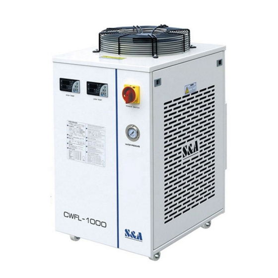
Page 8: Product Outlines & Parts
TY-JS-211220-009 III. Product Outlines & Parts Temperature Controller (laser head circuit) Temperature Controller (laser circuit) Power Switch Water Pressure Gauge Air Outlet Water Inlet L Water Supply Inlet (laser circuit) Water Outlet L (laser circuit) Water Level Gauge Air Inlet (Filter Gauze) Water Outlet H (optics circuit) -
Page 9: Installation
TY-JS-211220-009 IV. Installation 1. Open the package and check whether the machine is in good condition and whether the accessories are complete. 2. Please ensure that the working voltage of the chiller is stable and normal. Because the refrigeration compressor is sensitive to the power supply voltage, the normal working voltage of our company's standard products is 210~240V (110V model is 100~120V). - Page 10 TY-JS-211220-009 4. Determine the direction of the pipeline layout according to the water inlet and outlet of the chiller, and ensure that the waterway is clean and free of impurities, so as to prevent impurities from entering the waterway and causing blockage or pump failure. 5.
- Page 11 TY-JS-211220-009 (2) Exhaust Air After adding water for the first time or replacing water, exhaust the air in the water pump to start use, otherwise the equipment will be damaged. The exhaust method is as follows : Method 1: Under the state of shutting down, after adding water, remove the water outlet from the laser circuit (OUTLET L) and connect the water pipe, drain for 2 minutes, and then install it firmly.
- Page 12 TY-JS-211220-009 V. Operating States &Parameters Adjustment The new T-506A intelligent temperature controller does not need to adjust the controlling parameters under normal circumstance. It will self-adjust controlling parameters according to room temperature for meeting equipment cooling requirements. The new T-506B intelligent temperature controller is selected constant temperature control mode as factory setting with water temperature at 25℃.
-
Page 13: Operating States &Parameters Adjustment
TY-JS-211220-009 3.Alarm function (1) Alarm display: When alarm occurs, the error code and the temperature will be alternately displayed. (2) To suspend the alarm: Room Water Ultrahigh Ultrahigh Ultralow External Water flow temperature temperature room water water alarm alarm sensor sensor temperature temperature... - Page 14 TY-JS-211220-009 6.Advanced parameters adjustment case Order Code Items Value in Case 1 Value in Case 2 Temperature setting Temperature Difference Values Refrigeration return difference Way of control Alarm for over high water temperature Alarm for over low water temperature Alarm for over high room temperature Password The allowed highest water...
-
Page 15: Alarm & Output Terminal
TY-JS-211220-009 VI. Alarm & Output Terminal In order to guarantee the equipment will not be affected while abnormal situation happens to the chillers, the chillers are designed with alarm protection function. 1. Alarm output terminals and wiring diagram. 2.Alarm causes and working status table. Display Alarm Buzzer... -
Page 16: Maintenance
TY-JS-211220-009 VII.Maintenance The equipment must be shut down for maintenance, and the power supply must be cut off. The operation can only be carried out after 3 minutes, otherwise there will be a risk of electric shock. When the room temperature is lower than 2° C, the internal water must be drained when the machine is shut down for a long time. -
Page 17: Simple Troubleshooting
TY-JS-211220-009 VIII. Simple Troubleshooting Failure Failure Cause Approach Check and ensure the power interface Power cord is not plugged and the power plug is plugged in in place place and in good contact. Machine turned on but Open the electric box cover, check the unelectrified fuse and replace with a spare one if necessary. -
Page 18: Attachment - Schematic
TY-JS-211220-009 Attachment – Schematic CWFL-500/1000... - Page 19 TY-JS-211220-009 CWFL-1500/2000...
- Page 20 TY-JS-211220-009 CWFL-3000...
Need help?
Do you have a question about the CWFL-500 and is the answer not in the manual?
Questions and answers