Table of Contents
Advertisement
Available languages
Available languages
Quick Links
Advertisement
Table of Contents

Related Manuals for Supermicro X13SRA-TF


Summary of Contents for Supermicro X13SRA-TF
- Page 1 X13SRA-TF ENGLISH 繁體中文 简体中文 日本語 한국어 QUICK REFERENCE GUIDE Revision 1.00...
-
Page 3: About Standardized Warning Statements
Should you have questions or experience difficulty, contact Supermicro's Technical Support Department for assistance. Only certified technicians should attempt to install or configure components. Read this section in its entirety before installing or configuring components in the Supermicro chassis. WARNING: This product can expose you to chemicals including lead, known to the State of California to cause cancer and birth defects or other reproductive harm. - Page 4 X13SRA-TF QUICK REFERENCE GUIDE 限用物質含有情況標示聲明書 限 限 用 用 物 物 質 質 含 含 有 有 情 情 況 況 標 標 示 示 聲 聲 明 明 書 書 Declaration of the Presence Condition of the Restricted Substances Marking 設備名稱:主機板...
-
Page 5: Ami Bios Post Codes
X13SRA-TF QUICK REFERENCE GUIDE BIOS POST Codes AMI BIOS POST Codes About AMI BIOS POST Codes The table below lists some of AMI BIOS POST codes for this motherboard. For more information, refer to https://www. supermicro.com/manuals/other/AMI_AptioV_BIOS_POST_Codes_for_SM_Motherboards.pdf. Code Description 0x32 CPU post-memory initialization is started... -
Page 6: Device Installation
X13SRA-TF QUICK REFERENCE GUIDE M.2 Device Installation M.2 Device Installation This motherboard has two M.2 M-key sockets that support the 2280 and 22110 M.2 devices. One standoff and a screw are pre-installed into the position of each 22110 mounting hole. - Page 7 X13SRA-TF QUICK REFERENCE GUIDE 2280 M.2 Device Installation 2280 M.2 Device Installation 1. Locate the pre-installed standoff and screw. Remove the screw and set it aside. 2. Using a hex socket screwdriver, remove and then re-install the standoff to the posi- tion of the 2280 mounting hole.
- Page 8 X13SRA-TF QUICK REFERENCE GUIDE 22110 M.2 Device Installation 22110 M.2 Device Installation 1. Locate the pre-installed screw. Remove the screw and set it aside. 2. Insert the M.2 device into the M.2 socket at a 30-degree angle and press it down.
-
Page 9: Memory Population
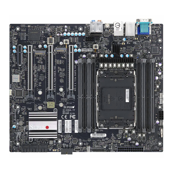
X13SRA-TF QUICK REFERENCE GUIDE Memory Population Memory Population Note: Unbalanced memory configuration decreases memory performance and is not recommended for Supermicro motherboards. Memory Population Table DDR5 Memory Population Table DDR5 DIMMF1 DIMMF2 DIMME1 DIMME2 DIMMA2 DIMMA1 DIMMB2 DIMMB1 DDR5 DDR5... - Page 10 UPERMICR X13SRA-TF . 1.00 uick efeRence uide Motherboard Layout and Features BACK PANEL I/O JUIDB1 UID-LED USB8 (USB3.2 GEN2X2) JPAC1 AUDIO FP HD AUDIO JSPDIF_OUT COM1 LAN2 LAN1 USB4/5 USB6/7 (USB3.2 GEN2) (USB3.2 GEN2) BMC LED JPUSB1 JPL2 JPW2 CTRL M.2-C02 LED...
-
Page 11: Jumpers And Connectors
• One Supermicro Motherboard • One GPU to CPU Power Cable • One Quick Reference Guide • One E1A Carrier for Intel W-3400 (112L) XCC CPU • One I/O Shield • One E1B Carrier for Intel W-2400 (64L) MCC CPU •... -
Page 12: Led Indicators
CPU and Memory Support The X13SRA-TF motherboard supports a single Intel Xeon W-2400 (64L)/ W-3400 (112L) series processor in Socket E1 LGA4677. The memory support is up to 512GB of ECC RDIMM or 2TB of 3DS RDIMM with speeds of up to 4800 MT/s (1DPC) or 4400 MT/s (2DPC) in eight ECC DDR5 (288-pin) SMD DIMM slots. -
Page 13: Back Panel I/O Connectors
otes • Graphics shown in this quick reference guide are for illustration only. Your components may or may not look exactly the same as drawings shown in this document. • Refer to Chapter 2 of the User's Manual for detailed information on jumpers, connectors, LED indicators, memory support and CPU/motherboard installation instructions. - Page 14 UPERMICR 美超微電腦股份有限公司 X13SRA-TF 快速參考指南版本 1.00 主機板元件配置圖 BACK PANEL I/O JUIDB1 UID-LED USB8 (USB3.2 GEN2X2) JPAC1 AUDIO FP HD AUDIO JSPDIF_OUT COM1 LAN2 LAN1 USB4/5 USB6/7 (USB3.2 GEN2) (USB3.2 GEN2) BMC LED JPUSB1 JPL2 JPW2 CTRL M.2-C02 LED FANB FANC M.2-C01 LED CTRL M.2-C02...
- Page 15 單一主機板包裝盒內容清單 • Supermicro 主機板 x1 • GPU 轉 CPU 電源線 x1 • • E1A 處理器托架 (適用 Intel W-3400 112L XCC CPU) x1 快速參考指南 • 後擋板 x1 • E1B 處理器托架 (適用 Intel W-2400 64L MCC CPU) x1 • SATA 訊號線 x6 跳線器/連接埠...
- Page 16 CPU and Memory Support 主機板 X13SRA-TF 支援單顆 Intel Xeon W-2400 (64L)/ W-3400 (112L) 系列處理器 (Socket E1 LGA4677 插槽 ) 。 記憶體支援 512GB ECC RDIMM 、 2TB 3DS RDIMM ;八根 288支針腳 ECC DDR5 SMD 記憶體插槽,傳輸速度最高可達 4800 MT/s (1DPC) 、 4400 MT/s (2DPC) 。...
- Page 17 備註 • 快速參考指南中圖例僅供安裝及操作說明使用,可能與實際產品外觀不同。 • 欲知更多跳線器/連接埠/指示燈/記憶體/主機板/中央處理器安裝相關資訊,請參閱 X13SrA-TF 使用手冊》第二章。 《 upermicro 中央處理器與散熱器安裝 註:E1A 處理器托架適用 W-3400 (112L) XCC CPU。E1B 處理器托架適用 W-2400 (64L) MCC CPU。此二款處理器托架皆隨主機板附上。 安裝 CPU 前請確認處理器托架的拉桿已壓回定位 (如下圖所示)。接著對齊 CPU 針腳1 及處理器托架上的空心三角形、 CPU 金屬接觸點朝上。小心謹慎地將 CPU 傾斜卡入下圖標記 A 的處理器托架凸榫,再將 CPU 的另一端放入下圖標記 B 的處理器 托架凸榫。 處理器托架上的空心三角形...
- Page 18 UPERMICR 美超微电脑股份有限公司 X13SRA-TF 快速参考指南版本1.00 主板布局和功能 I/O后面板 JUIDB1 UID-LED USB8 (USB3.2 GEN2X2) JPAC1 AUDIO FP HD AUDIO JSPDIF_OUT COM1 LAN2 LAN1 USB4/5 USB6/7 (USB3.2 GEN2) (USB3.2 GEN2) BMC LED JPUSB1 JPL2 JPW2 CTRL M.2-C02 LED FANB FANC M.2-C01 LED CTRL M.2-C02 JPL1 (PCIe 5.0 X4)
- Page 19 包装内容 • Supermicro 13SRA-TF主板x1 • GPU转CPU电源线x1 • 快速参考指南x1 • Intel W-3400 (112L) XCC CPU E1A 托架x1 • I/O扩展板x1 • Intel W-2400 (64L) MCC CPU E1B 托架x1 • SATA连接线x6 跳线和接口 跳线 跳线 描述说明 默认设置 JBT1 清除CMOS信息(板载) 清除CMOS信息的短接焊盘 JCMOS 清除CMOS信息(板载) 针脚1-2 (正常) JPAC1 HD自动启用/禁用...
- Page 20 板载电源 LED 绿灯保持亮起:开机 UID-LED 单元标识符(UID) LED 蓝灯亮起:设备已识别 CPU和内存支持 X13SRA-TF主板支持单个Intel Xeon (英特尔至強) W-3400 (112L)/ W-2400 (64L)系列处理器(插槽E1 LGA4677)。最 大支持内存为512GB ECC RDIMM 和 2TB 3DS RDIMM,最高速度 4800 MT/s (1DPC) 和 4400 MT/s (2DPC) 采用8根 ECC DDR5 (288针) SMD DIMM 为确保获得最佳系统性能,请在配置系统内存时安装相同类型和大小的内存模块;如果安装不同速度的内存模块,它们 将以最低安装内存模块速度运行。 备注:1) 要进行内存优化,请仅使用经Supermicro验证的DIMM模块。有关最新内存更新,请访问我们的网站...
- Page 21 备注 • 此快速参考指引中显示的图片,仅用于图示目的。您的组件可能与本文档中所 示的图片不同。 • 有关跳线、接口、LED指示灯、内存支持和CPU/主板安装说明的详细信息,请 参阅《用户手册》第2章 CPU和散热器安装 备注:若采用W-3400 (112L) XCC CPU,确保使用CPU托架 E1A。若采用W-2400 (64L) MCC CPU,确保使用CPU托架 E1B。 我们的附件套装包含2个CPU托架。 安装前,确保处理器托架上的操纵杆已按下,如下所示。抓住处理器,使LGA封装面(金色触点)朝上。以针脚1为基准, 小心对准处理器一端并将其扣入标有A的闭锁中,然后将处理器的另一端扣入标有B的闭锁。 托架上的三角形 托架底视图 CPU 针脚1 处理器托架部件 托架E1A 托架E1B (W-3400 112L XCC CPU) (W-2400 64L MCC CPU) 在安装处理器前, 确保已将拉杆 向下按压。 Processor Heatsink Module (PHM) 处理器托架部件...
- Page 22 UPERMICR X13SRA-TF クイック参照ガイド 1.00版 マザーボードのレイアウトと機能 I/O バックパネル JUIDB1 UID-LED USB8 (USB3.2 GEN2X2) JPAC1 AUDIO FP HD AUDIO JSPDIF_OUT COM1 LAN2 LAN1 USB4/5 USB6/7 (USB3.2 GEN2) (USB3.2 GEN2) BMC LED JPUSB1 JPL2 JPW2 CTRL M.2-C02 LED FANB FANC M.2-C01 LED CTRL M.2-C02...
- Page 23 パッケージ内容 • Supermicro マザーボード 1枚 • GPU - CPU 電源ケーブル1本 • クイック参照ガイド 1冊 • E1A キャリア 1個(Intel W-3400 112L XCC CPU 用) • I/O シールド 1個 • E1B キャリア 1個(Intel W-2400 64L MCC CPU 用) • SATA ケーブル 6本 ジャンパーおよびコネクタ...
- Page 24 M.2-C01/M.2-C02 用 M.2 LED 緑色に点滅:デバイス作動中 電源 LED オンボード電源 LED 緑色に点灯:電源オン UID-LED ユニット ID (UID)LED ブルー オン:ユニットの識別 CPU およびメモリサポート X13SRA-TF マザーボードは、Socket E1 LGA4677で Intel Xeon W-2400(64L)/W-3400(112L)シリーズプロセッ サをサポートします。搭載可能なメモリーの最大容量についてECC RDIMMの場合は最大512GBまで、3DS RDIMMの場合は最 大2TBまでです。メモリーの速度について1DPC(メモリ4本搭載)の場合は4800 MT/sまで、2DPC(メモリ8本搭載)の場合は 4400 MT/sまでです。 これらの DIMM スロットにタイプとサイズが同じメモリモジュールのペアを装着した場合、インターリーブメモリが生成されてメモリパフォーマン スが向上します。 注記:1) メモリの最適化には、Supermicro によって検証済みの DIMM モジュールのみを使用してください。最新のメモリアップデ ートについては、当社のウェブサイト(https://www.supermicro.com/products/motherboard)を参照してく ださい。...
- Page 25 注記 • 本クイック参照ガイドにある図は参考用です。本書に記載されている図面とお客様のコンポ ーネントが全く同一であるとは限りません。 • ジャンパ、コネクタ、LED インジケータ、対応メモリ、および CPU /マザーボードの設置方 法に関する詳細については、ユーザーマニュアルの第 2 章を参照してください。 CPU とヒートシンクの設置方向 注:W-3400 (112L) XCC CPU の場合は、必ず CPU キャリア E1A を使用してください。W-2400 (64L) MCC CPU の場合 は、必ず CPU キャリア E1B を使用してください。アクセサリキットには CPU キャリアが 2 個同梱されています。 取り付け前に、プロセッサーキャリアのレバーが下図のように押し下げられていることを確認してください。LGA (金色の接点)が上になるよう に、プロセッサーを持ちます。ピン 1 をガイドにしてプロセッサの一方の端を A とマーク付けされたラッチに慎重に揃えて差し込み、もう片方の端 を...
- Page 26 UPERMICR X13SRA-TF 간편 가이드 개정판 1.00 메인보드 레이아웃 및 특징 후면패널 I/O JUIDB1 UID-LED USB8 (USB3.2 GEN2X2) JPAC1 AUDIO FP HD AUDIO JSPDIF_OUT COM1 LAN2 LAN1 USB4/5 USB6/7 (USB3.2 GEN2) (USB3.2 GEN2) BMC LED JPUSB1 JPL2 JPW2 CTRL M.2-C02 LED FANB FANC M.2-C01 LED...
- Page 27 제품 구성물 • Supermicro 메인보드 1개 • GPU와 CPU 연결 전원 케이블 1개 • 간편 가이드 1부 • Intel W-3400 (112L) XCC CPU용 E1A 캐리어 1개 • I/O 쉴드 1개 • Intel W-2400 (64L) MCC CPU용 E1B 캐리어 1개 • SATA 케이블 6개...
- Page 28 DIMM 슬롯에 동일한 유형 및 크기의 메모리 모듈 쌍을 채우면 인터리브 메모리가 발생하여 메모리 성능이 향상됩 니다. 주: 1) 메모리 최적화를 위해 반드시 Supermicro의 인증을 받은 DIMM 모듈을 사용해야 합니다. 최신 메모리 업 데이트는, 저희 웹사이트 https://www.supermicro.com/products/motherboard를 참조하세요. 2) 전원 코드는 반드시 마지막에 연결하고 하드웨어 구성품을 추가, 제거, 변경하기 전에는 반드시 전원 코드...
- Page 29 참고 • 본 간편 설명서의 그림들은 예시로만 사용됩니다. 실제 부품은 이 문서에 표 시된 도면과 동일하지 않을 수 있습니다. • 점퍼, 커넥터, LED 표시등, 메모리 지원 및 CPU /메인보드 설치 지침에 대 한 자세한 내용은 사용 설명서의 2장을 참조하십시오. CPU 및 방열판 설치 주: W-3400 (112L) XCC CPU의...
- Page 30 X13SRA-TF QUICK REFERENCE GUIDE Notes Notes...
Need help?
Do you have a question about the X13SRA-TF and is the answer not in the manual?
Questions and answers