Table of Contents
Advertisement
Available languages
Available languages
Quick Links
Advertisement
Table of Contents

Related Manuals for Supermicro X13SAE


Summary of Contents for Supermicro X13SAE
- Page 1 X13SAE X13SAE-F ENGLISH 繁體中文 简体中文 日本語 한국어 QUICK REFERENCE GUIDE Revision 1.0a...
-
Page 3: About Standardized Warning Statements
Should you have questions or experience difficulty, contact Supermicro's Technical Support Department for assistance. Only certified technicians should attempt to install or configure components. Read this section in its entirety before installing or configuring components in the Supermicro chassis. WARNING: This product can expose you to chemicals including lead, known to the State of California to cause cancer and birth defects or other reproductive harm. - Page 4 X13SAE/X13SAE-F QUICK REFERENCE GUIDE 限用物質含有情況標示聲明書 限 限 用 用 物 物 質 質 含 含 有 有 情 情 況 況 標 標 示 示 聲 聲 明 明 書 書 Declaration of the Presence Condition of the Restricted Substances Marking 設備名稱:主機板...
-
Page 5: Ami Bios Post Codes
X13SAE/X13SAE-F QUICK REFERENCE GUIDE BIOS POST Codes AMI BIOS POST Codes About AMI BIOS POST Codes The table below lists some of AMI BIOS POST codes for this motherboard. For more information, refer to https://www. supermicro.com/manuals/other/AMI_AptioV_BIOS_POST_Codes_for_SM_Motherboards.pdf. Code Description 0x32 CPU post-memory initialization is started... -
Page 6: Device Installation
X13SAE/X13SAE-F QUICK REFERENCE GUIDE M.2 Device Installation Instructions M.2 Device Installation Instructions M.2 Device Installation This motherboard has three PCIe 4.0 M.2 M-key sockets that support the M.2 2280 module. One standoff is pre-installed into 2280 the position of 2280 mounting hole. Refer... - Page 7 X13SAE/X13SAE-F QUICK REFERENCE GUIDE Notes Notes...
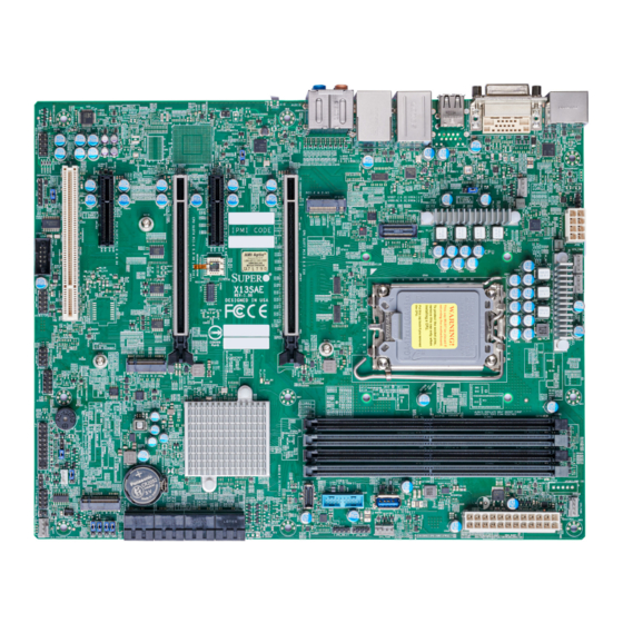
- Page 8 UPERMICR X13SAE / X13SAE-F . 1.0a uick efeRence uide Motherboard Layout and Features BACK PANEL I/O LED4 AUDIO_FP HDMI AUDIO LAN2 LAN1 IPMI_LAN USB8/9 (3.2 (10Gb)) USB7 (3.2 (10Gb)) USB0/1 USB10 (3.2 (20Gb)) BMC_HB_LED JPL2 CPU_FAN1 JPL1 JPAC1 JPW2 MAC CODE PCI-E M.2-M3...
-
Page 9: Jumpers And Connectors
Back Panel DisplayPort 1.4a and High Definition Multimedia Interface (HDMI) 2.0b Port Digital Video Interface (DVI-D) I-SATA0 - I-SATA7 Intel® Serial ATA (SATA 3.0) Ports (6 Gb/second) IPMI_LAN Dedicated IPMI LAN Port (X13SAE-F only) Front Control Panel Header Chassis Intrusion Header JLED1 3-pin Power LED Header... -
Page 10: Led Indicators
Notes: 1) For memory optimization, use only DIMM modules that have been validated by Supermicro. For the latest memory updates, please refer to our website at http://www.supermicro.com/products/motherboard. -
Page 11: Cpu Installation
7. USB1: USB 2.0 Port 17. Line In (10 Gb, Type-A) 13. USB9: USB 3.2 Gen. 2x1 Port 3. VGA Port (X13SAE-F only) 8. LAN1: 1Gb LAN Port 18. Line Out (10 Gb, Type-A) 9. USB7: USB 3.2 Gen. 2x1 Port 4. - Page 12 UPERMICR 美超微電腦股份有限公司 X13SAE / X13SAE-F 快速參考指南版本 1.0a 主機板元件配置圖 BACK PANEL I/O LED4 AUDIO_FP HDMI AUDIO LAN2 LAN1 IPMI_LAN USB8/9 (3.2 (10Gb)) USB7 (3.2 (10Gb)) USB0/1 USB10 (3.2 (20Gb)) BMC_HB_LED JPL2 CPU_FAN1 JPL1 JPAC1 JPW2 MAC CODE PCI-E M.2-M3 BMC CODE...
- Page 13 組態資料清除 (內建) 設為短路清除 CMOS 資料 針腳 1-4:外接喇叭 喇叭/蜂鳴器 針腳 3-4:蜂鳴器 (預設值) JPAC1 針腳 1-2 (啟用) 啟用/停用音源 JPG1 啟用/停用 VGA (僅限 X13SAE-F) 針腳 1-2 (啟用) JPL1, JPL2 啟用/停用 LAN1/LAN2 針腳 1-2 (啟用) JPME2 Intel 製造模式 針腳 1-2 (正常) JWD1 啟用系統監控 (Watch Dog) 功能...
- Page 14 CATERR_LED 主機故障識別燈 (需配合相關軟體) 橘燈恆亮:該機故障 LED4 單位識別指示燈 (僅限 X13SAE-F, IPMI) 藍燈恆亮:識別中 PWR_LED 內建電源指示燈 綠燈恆亮:內建電源已開啟 中央處理器和記憶體支援 主機板 X13SAE/X13SAE-F 支援單顆第十二/十三代 Intel Core i9/i7/i5/i3 系列處理器。記憶體支援 128GB Unbuffered (UDIMM) ECC/ Non-ECC DDR5 及四根 288 支針腳記憶體插槽,傳輸速度最高可達 4400MT/s 。欲取得雙通道效能,請安裝成對相同型號與速 ; 度的記憶體。 註: 請安裝使用本公司所認可記憶體模組以達記憶體模組最佳化。更多記憶體模組相關訊息,請參閱本公司網頁 http://www.supermicro.com/products/motherboard 。 增加、移除和更換任何硬體元件前,請務必先拔掉電源線。待確實完成所有程序後,再重新連接電源線。 3) Unbuffered DIMM...
- Page 15 備註 • 快速參考指南中圖例僅供安裝及操作說明使用,可能與實際產品外觀不同。 • 欲知更多跳線器/連接埠/指示燈/記憶體/主機板/中央處理器安裝相關資訊,請參閱 X13SAe / X13SAe-F 使用手冊》第二章。 《 upermicro 中央處理器安裝 散熱器安裝 針腳 1 CPU 校準缺口 螺絲 螺絲 螺絲 CPU 固定底座 校準點 主機板 前控制面板配置 (JF1) Power Button #1~2 Ground #1~2 電源鍵 接地 Reset Button #3~4 Ground #3~4 重設鍵 接地...
- Page 16 UPERMICR 美超微电脑股份有限公司 X13SAE / X13SAE-F 快速参考指南版本1.0a 主板布局和功能 I/O后面板 LED4 AUDIO_FP HDMI AUDIO LAN2 LAN1 IPMI_LAN USB8/9 (3.2 (10Gb)) USB7 (3.2 (10Gb)) USB0/1 USB10 (3.2 (20Gb)) BMC_HB_LED JPL2 CPU_FAN1 JPL1 JPAC1 JPW2 MAC CODE PCI-E M.2-M3 BMC CODE COM1 BAR CODE...
- Page 17 CPU_FAN1, CPU_FAN2:CPU风扇接脚 SYS_FAN1 - SYS_FAN3 SYS_FAN1 - SYS_FAN3:系统风扇接脚 DP , HDMI 后面板DisplayPort 1.4a和高清多媒体接口 (HDMI) 2.0b 端口 数字视频接口 (DVI-D) I-SATA0 - I-SATA7 Intel串行ATA (SATA 3.0) 端口 (6 Gb/秒) IPMI_LAN 专用IPMI LAN端口 (仅限X13SAE-F) 前端控制面板接脚 机箱侵入接脚 JLED1 3针电源LED接脚 JPI2C1 电源SMBus I C接脚 (仅限X13SAE-F) JPW1 24针ATX主电源接口(必需)...
- Page 18 BMC_HB_LED X13SAE-F:BMC心跳LED X13SAE-F:绿灯闪烁(BMC正常) CATERR_LED 灾难性错误LED 橙灯亮起:系统灾难性错误 LED4 装置标识符 (UID) LED (X13SAE-F,仅限IPMI) 蓝灯闪烁:装置标识符 PWR_LED 板载电源LED 绿灯保持亮起:开机 CPU和内存支持 X13SAE/X13SAE-F主板支持单个第12/13代Intel Core i9/i7/i5/i3系列处理器,最高128GB无缓冲 (UDIMM) ECC/非ECC DDR5内存,在四个288针内存插槽中速度高达4400MT/s。在这些DIMM插槽中填充一对相同类型和大小的内存模块将 产生交错内存,这将提高内存性能。 备注:1)要进行内存优化,请仅使用经Supermicro超微验证的DIMM模块。有关最新的内存更新,请访问我们的网站 http://www.supermicro.com/products/motherboard。 2)始终最后连接电源线,并在添加、移除或更换任何硬件组件之前始终将其断开。 DIMM内存安装 朝向CPU DIMMA1 (黑色插槽) DIMMA2 (灰色插槽) DIMMB1 (黑色插槽) DIMMB2 (灰色插槽) 内存占用指南 安装内存模块时,应按照以下顺序插入 DIMM 插槽:DIMMA2,DIMMB2,之后DIMMA1,DIMMB1。...
- Page 19 OH/Fan Fail LED NIC2 LED NIC2 LED NIC1 LED NIC1 LED Vcc (X13SAE) Vcc (X13SAE) HDD LED HDD LED UID SW (X13SAE-F) UID SW (X13SAE-F) 电源LED Power LED 接地 Ground 后面板I/O接口 1. DisplayPort 1.4a 6. USB0:USB 2.0端口 11. LAN2:2.5Gb LAN端口...
- Page 20 UPERMICR X13SAE / X13SAE-F クイック参照ガイド 1.0a版 マザーボードのレイアウトと機能 I/O バックパネル LED4 AUDIO_FP HDMI AUDIO LAN2 LAN1 IPMI_LAN USB8/9 (3.2 (10Gb)) USB7 (3.2 (10Gb)) USB0/1 USB10 (3.2 (20Gb)) BMC_HB_LED JPL2 CPU_FAN1 JPL1 JPAC1 JPW2 MAC CODE PCI-E M.2-M3 BMC CODE COM1 BAR CODE...
- Page 21 SYS_ファン 1 - SYS_ファン 3︓システムファンヘッダー DP、HDMI バックパネルDisplayPort 1.4a/高精細度マルチメディアインターフェース (HDMI) 2.0b ポート デジタルビデオインターフェース(DVI-D) I-SATA0 - I-SATA7 Intel シリアル ATA (SATA 3.0) ポート (6 Gb/秒) IPMI_LAN IPMI 専用 LAN ポート (X13SAE-F のみ) フロント コントロールパネル ヘッダー シャーシイントルージョンヘッダー JLED1 3ピン 電源 LED ヘッダー JPI2C1 電源 SMBus I C ヘッダー...
- Page 22 ユニット ID (UID) LED (X13SAE-F、IPMI のみ) 緑色に点灯︓ユニット ID PWR_LED オンボード電源 LED 緑色に点灯︓電源オン CPU およびメモリサポート X13SAE/X13SAE-F マザーボードは、第 12/13 世代 Intel Core i9/i7/i5/i3 シリーズプロセッサ、最大 128GB のバッファーな し (UDIMM) ECC/Non-ECC DDR5 メモリ、4 つの 288 ピンメモリスロットにある最大 4400MT/s の速度でサポートします。これ らの DIMM スロットにタイプとサイズが同じメモリモジュールのペアを装着した場合、インターリーブメモリが生成されてメモリパフォーマンスが 向上します。 注記︓1) メモリの最適化には、Supermicro によって検証済みの DIMM モジュールのみを使用してください。最新のメモリアップデ ートについては、当社のウェブサイト(http://www.supermicro.com/products/motherboard)を参照してくだ...
- Page 23 OH/ファン障害 LED NIC2 LED NIC2 LED NIC1 LED NIC1 LED Vcc (X13SAE) Vcc (X13SAE) HDD LED HDD LED UID SW (X13SAE-F) UID SW (X13SAE-F) 電源LED Power LED グランド Ground バックパネル I/O コネクタ 1. DisplayPort 1.4a 6. USB0︓USB 2.0 ポート 11. LAN2︓2.5Gb LAN ポート...
- Page 24 UPERMICR X13SAE / X13SAE-F 간편 참조 가이드 개정판 1.0a 메인보드 레이아웃 및 특징 I/O 후면 패널 LED4 AUDIO_FP HDMI AUDIO LAN2 LAN1 IPMI_LAN USB8/9 (3.2 (10Gb)) USB7 (3.2 (10Gb)) USB0/1 USB10 (3.2 (20Gb)) BMC_HB_LED JPL2 CPU_FAN1 JPL1 JPAC1 JPW2 MAC CODE PCI-E M.2-M3...
- Page 25 CMOS 초기화용 쇼트패드 핀 1~4: 외부 스피커 스피커/버저 핀 3-4: 버저(기본값) JPAC1 HD 오디오 사용/사용 안 함 핀 1-2(사용) JPG1 VGA 사용/사용 안 함(X13SAE-F 전용) 핀 1-2(사용) JPL1, JPL2 LAN1/LAN2 사용/사용 안 함 핀 1-2(사용) JPME2 ME 제조 모드 핀 1-2(정상) JWD1 Watch Dog 기능...
- Page 26 ECC/Non-ECC DDR5 메모리를 지원합니다(4개의 288핀 메모리 슬롯에서 최대 속도 4400MT/s). DIMM 슬롯에 동 일한 유형 및 크기의 메모리 모듈 쌍을 채우면 인터리브 메모리가 발생하여 메모리 성능이 향상됩니다. 참고: 1) 메모리 최적화를 위해 반드시 Supermicro의 인증을 받은 DIMM 모듈을 사용해야 합니다. 최신 메모리 업데이트는 웹사이트(http://www.supermicro.com/products/motherboard)를 참조하십시오.
- Page 27 2. HDMI 2.0b 포트 7. USB1: USB 2.0 포트 17. 라인 입력 (10Gb, 타입 A) 13. USB9: USB 3.2 Gen. 2x1 포트 3. VGA 포트(X13SAE-F 전용) 8. LAN1: 1Gb LAN 포트 18. 라인 출력 (10Gb, 타입 A) 4. 디지털 비디오 인터페이스...
- Page 28 X13SAE/X13SAE-F QUICK REFERENCE GUIDE Notes Notes...
- Page 29 X13SAE/X13SAE-F QUICK REFERENCE GUIDE Notes Notes...
- Page 30 X13SAE/X13SAE-F QUICK REFERENCE GUIDE Notes Notes...
Need help?
Do you have a question about the X13SAE and is the answer not in the manual?
Questions and answers