Table of Contents
Advertisement
Quick Links
Advertisement
Table of Contents

Related Manuals for Supermicro X12DSC-A6


Summary of Contents for Supermicro X12DSC-A6
- Page 1 X12DSC-A6 USER'S MANUAL Revision 1.0...
- Page 2 State of California, USA. The State of California, County of Santa Clara shall be the exclusive venue for the resolution of any such disputes. Supermicro's total liability for all claims will not exceed the price paid for the hardware product.
- Page 3 (in Socket P+ LGA 4189) with up to 40 CPU cores and a Thermal Design Power (TDP) of up to 270W. Built with the Intel C621A chipset, the X12DSC-A6 supports up to 4 TB of 3DS LRDIMM/LRDIMM/3DS RDIMM/RDIMM DDR4 ECC memory with speeds of 3200/2933/2666 MHz in 16 DIMMs, and up to 4 TB of Intel Optane™...
- Page 4 Super X12DSC-A6 User's Manual Conventions Used in the Manual Special attention should be given to the following symbols for proper installation and to prevent damage done to the components or injury to yourself: Important: Important information given to ensure proper system installation or to relay safety precautions.
- Page 5 Super Micro Computer, Inc. 980 Rock Ave. San Jose, CA 95131 U.S.A. Tel: +1 (408) 503-8000 Fax: +1 (408) 503-8008 Email: marketing@supermicro.com (General Information) support@supermicro.com (Technical Support) Website: www.supermicro.com Europe Address: Super Micro Computer B.V. Het Sterrenbeeld 28, 5215 ML...
-
Page 6: Table Of Contents
Super X12DSC-A6 User's Manual Table of Contents Chapter 1 Introduction 1.1 Overview ..........................8 1.2 Processor and Chipset Support ..................17 1.3 Special Features ........................17 1.4 System Health Monitoring ....................18 1.5 ACPI Features ........................18 1.6 Power Supply ........................19 1.7 Serial Port ...........................19 1.8 Intel®... - Page 7 Preface 4.6 Security ..........................148 4.7 Boot ...........................153 4.8 Save & Exit ........................155 Appendix A BIOS POST Codes A.1 BIOS POST Codes ......................157 Appendix B Software B.1 Microsoft Windows OS Installation ...................158 B.2 Driver Installation ......................160 B.3 SuperDoctor 5 .........................161 ® B.4 BMC ..........................162 B.5 Logging into the BMC (Baseboard Management Controller) ...........162 Appendix C Standardized Warning Statements...
-
Page 8: Chapter 1 Introduction
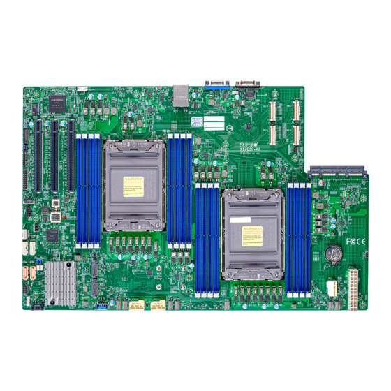
Chapter 1 Introduction Congratulations on purchasing your computer motherboard from an industry leader. Supermicro motherboards are designed to provide you with the highest standards in quality and performance. 1.1 Overview This motherboard was designed to be used with a Supermicro-proprietary chassis as an integrated server platform. - Page 9 Chapter 1: Introduction X12DSC-A6 Motherboard Image Note: All graphics shown in this manual were based upon the latest PCB revision available at the time of publication of the manual. The motherboard you received may or may not look exactly the same as the graphics shown in this manual.
- Page 10 Super X12DSC-A6 User's Manual X12DSC-A6 Motherboard Layout (not drawn to scale) UID_LED1 JUIDB1 JNVI2C1 COM1 JSTBY1 P1_NVME0 LEDM1 BMC_LAN USB0/1 (3.0) JNCSI1:NCSI interface for IPMI shared LAN P1_NVME3 BAR CODE BIOS LICENSE JNCSI1 BMC CODE P1_NVME2 JUID X12DSC-A6 P1_NVME1 REV:1.00...
- Page 11 JNCSI1:NCSI interface for IPMI shared LAN P1_NVME3 BAR CODE BIOS LICENSE JNCSI1 BMC CODE JNCSI1 P1_NVME2 P1_NVME2 P1_NVME1 JNCSI1_SEL JUID JUID X12DSC-A6 P1_NVME1 P1-AIOM PCI-E 4.0 X16 REV:1.00 DESIGNED IN USA JWD1 JWD1 LEDPWR CPU2 P1-AIOM PCI-E 4.0 X16 P2-DIMMC1 P2-DIMMD1 JFP1...
- Page 12 Super X12DSC-A6 User's Manual Quick Reference Table Jumper Description Default Setting JBT1 CMOS Clear Open (Normal) Pins 1-2 (AIOM, default) JNCSI1_SEL NCSI to JNCSI1 or AIOM Pins 2-3 (JNCSI1) JPME2 ME Manufacturing Recovery Pins 1-2 (Normal) Pins 1-2 (UID Enabled)
- Page 13 Chapter 1: Introduction Connector Description P2 SLOT1 - P2 SLOT3 CPU2 PCIe 4.0 x16 Slots Intel PCH Powered S-SATA 3.0 Ports (with support of SuperDOM devices) S-SATA0, S-SATA1 * DOM: Disk on Module S-SATA2, S-SATA3 Intel PCH SATA 3.0 Ports (with support of RAID 0, 1, 5, 10) S-SGPIO1 Serial General Purpose I/O Connection Header (for S-SATA0/1/2/3) SRW1 - SRW4...
- Page 14 Super X12DSC-A6 User's Manual Motherboard Features Motherboard Features • Supports dual 3rd Gen. Intel Xeon Scalable Processors (in Socket P+ LGA 4189) with up to 40 cores per CPU and a Thermal Design Power (TDP) of up to 270W Memory •...
- Page 15 Note 1: The CPU maximum TDP is subject to chassis and heatsink cooling restrictions. For proper thermal management, please check the chassis and heatsink specifications. Note 2: For BMC configuration instructions, please refer to the Embedded BMC Con- figuration User's Guide available at http://www.supermicro.com/support/manuals/.
- Page 16 Super X12DSC-A6 User's Manual System Block Diagram X12DSC-A6 DIMMG1 DIMMC1 DIMMG1 DIMMC1 DIMMH1 DIMMD1 DIMMH1 DIMMD1 DIMME1 DIMMA1 DIMME1 DIMMA1 DIMMF1 DIMMB1 DIMMF1 DIMMB1 CPU 2 CPU 1 UPI0[0:19] UPI2[0:19] PCI-E X16-Gen4 PCI-E X16-Gen4 AIOM JPCIE1 PE0[0:15] PE0[0:15] UPI1[0:19] UPI1[0:19]...
-
Page 17: Processor And Chipset Support
1.2 Processor and Chipset Support Built upon the functionality and capability of the 3rd Gen. Intel Xeon Scalable Processors (Socket P+) and the Intel C621A chipset, the X12DSC-A6 motherboard increases energy efficiency, and system performance for a multitude of applications such as high-end, high- performance enterprise storage, database storage, and virtualization server platforms. -
Page 18: System Health Monitoring
Plug and Play, and an operating system-independent interface for configuration control. ACPI leverages the Plug and Play BIOS data structures, while providing a processor architecture-independent implementation that is compatible with appropriate Windows operating systems. For detailed information regarding OS support, please refer to the Supermicro website. -
Page 19: Power Supply
1.7 Serial Port The X12DSC-A6 motherboard supports one serial communication connection. COM1 port can be used for input/output. The UART provides legacy speeds with a baud rate of up to 115.2 Kbps as well as an advanced speed with baud rates of 250 K, 500 K, or 1 Mb/s, which support high-speed serial communication devices. -
Page 20: Chapter 2 Installation
Super X12DSC-A6 User's Manual Chapter 2 Installation 2.1 Static-Sensitive Devices Electrostatic Discharge (ESD) can damage electronic components. To avoid damaging your motherboard, it is important to handle it very carefully. The following measures are generally sufficient to protect your equipment from ESD. -
Page 21: Processor And Heatsink Installation
Thermal grease is pre-applied on a new heatsink. No additional thermal grease is needed. • Refer to the Supermicro website for updates on processor and memory support. • All graphics in this manual are for illustrations only. Your components may look different. - Page 22 Super X12DSC-A6 User's Manual 1. The 3rd Gen. Intel Xeon Scalable Processor Processor Top View (3D) CPU Key Pin 1 = Cutout = CPU Key = Pin 1 Processor Top View...
- Page 23 Chapter 2: Installation 2. The Processor Carrier Carrier Bottom View...
- Page 24 Super X12DSC-A6 User's Manual 3. Heatsink Note: Exercise extreme care when handling the heatsink. Pay attention to the edges of heatsink fins which can be sharp! To avoid damaging the heatsink, please do not apply excessive force on the fins when handling the heatsink.
- Page 25 Chapter 2: Installation Overview of the CPU Socket The CPU socket is protected by a plastic protective cover. Plastic Protective Cover CPU Socket...
- Page 26 Super X12DSC-A6 User's Manual Overview of the Processor Carrier Assembly The processor carrier assembly contains a 3rd Gen. Intel Xeon Scalable processor and a processor carrier. Carefully follow the instructions given in the installation section to place a processor into the carrier to create a processor carrier.
- Page 27 Chapter 2: Installation Overview of the Processor Heatsink Module The Processor Heatsink Module (PHM) contains a heatsink, a processor carrier, and a 3rd Gen. Intel Xeon Scalable processor. 1. Heatsink (with Thermal Grease) 2. Processor Carrier 3. The 3rd Gen. Intel Xeon Scalable Processor Bottom View 4.
- Page 28 Super X12DSC-A6 User's Manual Creating the Processor Carrier Assembly The processor carrier assembly contains a 3rd Gen. Intel Xeon Scalable processor and a processor carrier. To create the processor carrier assembly, please follow the steps below: Note: Before installation, be sure to follow the instructions given on pages 1 and 2 of this chapter to properly prepare yourself for installation.
- Page 29 Chapter 2: Installation 3. Locate the lever on the CPU socket and press the lever down as shown below. 4. Using Pin 1 as a guide, carefully align the CPU keys (A & B) on the processor against the CPU keys on the carrier (a & b) as shown in the drawing below. 5.
- Page 30 Super X12DSC-A6 User's Manual Creating the Processor Heatsink Module (PHM) After creating the processor carrier assembly, please follow the instructions below to mount the processor carrier into the heatsink to form the processor heatsink module (PHM). Note: If this is a new heatsink, the thermal grease has been pre-applied on the un- derside.
- Page 31 Chapter 2: Installation Preparing the CPU Socket for Installation This motherboard comes with a plastic protective cover installed on the CPU socket. Remove it from the socket by following the instructions given in the drawings below. Removing the Plastic Protective Cover from the Socket 1.
- Page 32 Super X12DSC-A6 User's Manual Preparing to Install the Processor Heatsink Module (PHM) into the CPU Socket After assembling the Processor Heatsink Module (PHM), you are ready to install it into the CPU socket. To ensure the proper installation, please follow the procedures below: 1.
- Page 33 Chapter 2: Installation Installing the Processor Heatsink Module (PHM) 1. Align peek nut "A", which is next to the triangle (Pin 1) on the heatsink, against threaded fastener "a" on the CPU socket. Then align peek nuts "B", "C", "D" on the heatsink against threaded fasteners "b", "c", "d"...
- Page 34 Super X12DSC-A6 User's Manual Removing the Processor Heatsink Module from the CPU Socket Before removing the processor heatsink module (PHM) from the motherboard, unplug the AC power cord from all power supplies after shutting down the system. Then follow the steps below: 1.
- Page 35 Chapter 2: Installation Removing the Processor Carrier Assembly from the Processor Heatsink Module (PHM) To remove the processor carrier assembly from the PHM, please follow the steps below: 1. Detach four plastic clips (marked a, b, c, d) on the processor carrier assembly from the four corners of heatsink (marked A, B, C, D) in the drawings below.
- Page 36 Super X12DSC-A6 User's Manual Removing the Processor from the Processor Carrier Assembly Once you have removed the processor carrier assembly from the PHM, you are ready to remove the processor from the processor carrier by following the steps below. 1. Unlock the lever from its locking position and push the lever upwards to disengage the processor from the processor carrier as shown in the right drawing below.
-
Page 37: Motherboard Installation
P1_NVME0 LEDM1 BMC_LAN USB0/1 (3.0) JNCSI1:NCSI interface for IPMI shared LAN P1_NVME3 BAR CODE BIOS LICENSE JNCSI1 BMC CODE P1_NVME2 JUID X12DSC-A6 P1_NVME1 REV:1.00 DESIGNED IN USA JWD1 CPU2 P1-AIOM PCI-E 4.0 X16 JFP1 JTPM1 CPU1 JIPMB1 S-SATA3 S-SATA2 M.2-HC_2 (PCI-E 4.0/S-SATA5) - Page 38 Super X12DSC-A6 User's Manual Installing the Motherboard 1. Install the I/O shield into the back of the chassis, if applicable. 2. Locate the mounting holes on the motherboard. See the previous page for the locations. 3. Locate the matching mounting holes on the chassis. Align the mounting holes on the motherboard against the mounting holes on the chassis.
-
Page 39: Memory Support And Installation
Memory Support The X12DSC-A6 supports up to 4 TB of 3DS LRDIMM/LRDIMM/3DS RDIMM/RDIMM DDR4 (288-pin) ECC memory with speeds of 3200/2933/2666 MHz in 16 memory slots and up to 4 TB of Intel Optane PMem 200 Series with speeds of up to 3200 MHz. - Page 40 2 CPUs & 14 DIMMs CPU1: P1-DIMMA1/P1-DIMME1/P1-DIMMC1/P1-DIMMG1/P1-DIMMB1/P1-DIMMF1/P1-DIMMD1/P1-DIMMH1 CPU2: P2-DIMMA1/P2-DIMME1/P2-DIMMC1/P2-DIMMG1/P2-DIMMB1/P2-DIMMF1 2 CPUs & 16 DIMMs CPU1: P1-DIMMA1/P1-DIMME1/P1-DIMMC1/P1-DIMMG1/P1-DIMMB1/P1-DIMMF1/P1-DIMMD1/P1-DIMMH1 Note CPU2: P2-DIMMA1/P2-DIMME1/P2-DIMMC1/P2-DIMMG1/P2-DIMMB1/P2-DIMMF1/P2-DIMMD1/P2-DIMMH1 Note: This memory configuration is recommended by Supermicro for optimal memory performance. Please use this configuration to maximize your memory performance.
- Page 41 Chapter 2: Installation Intel Optane PMem 200 Series Memory Population Table (with 16 Slots) Note: The Intel Optane Persistent (PMem) 200 Series are supported by the 3rd Gen. Intel Xeon Scalable (83xx/63xx/53xx/4314) processors. 16-DIMM Motherboard PMem Population within 1 CPU socket DDR4+PMem Mode AD Interleave...
- Page 42 Super X12DSC-A6 User's Manual DIMM Installation UID_LED1 JUIDB1 JNVI2C1 COM1 JSTBY1 P1_NVME0 LEDM1 BMC_LAN JNCSI1:NCSI interface for IPMI shared LAN USB0/1 (3.0) P1_NVME3 BAR CODE 1. Insert the desired number of DIMMs into the memory JNCSI1 BIOS LICENSE BMC CODE...
-
Page 43: Rear I/O Ports
P1_NVME0 LEDM1 BMC_LAN USB0/1 (3.0) JNCSI1:NCSI interface for IPMI shared LAN P1_NVME3 BAR CODE BIOS LICENSE JNCSI1 BMC CODE P1_NVME2 JUID X12DSC-A6 P1_NVME1 REV:1.00 DESIGNED IN USA JWD1 CPU2 P1-AIOM PCI-E 4.0 X16 JFP1 JTPM1 CPU1 JIPMB1 S-SATA3 S-SATA2 M.2-HC_2 (PCI-E 4.0/S-SATA5) - Page 44 Super X12DSC-A6 User's Manual COM Port One COM port hat supports serial link interface is on the motherboard. COM1 is located on the rear I/O panel of the motherboard. Refer to the layout below for the location of COM1. VGA Connections There is one VGA connection in your system.
- Page 45 2. (Internal Type-A) USB2 (3.0) LEDM1 BMC_LAN USB0/1 (3.0) JNCSI1:NCSI interface for IPMI shared LAN P1_NVME3 BAR CODE BIOS LICENSE JNCSI1 BMC CODE P1_NVME2 JUID X12DSC-A6 P1_NVME1 REV:1.00 DESIGNED IN USA JWD1 CPU2 P1-AIOM PCI-E 4.0 X16 JFP1 JTPM1 CPU1 JIPMB1 S-SATA3 S-SATA2 M.2-HC_2 (PCI-E 4.0/S-SATA5)
- Page 46 Super X12DSC-A6 User's Manual UID (Unit Identifier)/BMC Reset Switch and UID/BMC Reset LED Indicators A UID / BMC Reset switch (JUIDB1) is located on the rear side of the motherboard. This switch has dual functions. It can be used to identify a system unit that is in need of service, and it can also be used to reset the BMC settings.
-
Page 47: Front Control Panel
These connectors are designed specifically for use with Supermicro chassis. Refer to the figure below for the descriptions of the front control panel buttons and LED indicators. - Page 48 Super X12DSC-A6 User's Manual Front Control Panel LEDs Power Button Ground Reset Button Ground Power Fail (for LED6) 3.3V Red+ Blue+ (Blue LED_Cathode_UID) (Red OH/Fan Fail/PWR Fail for LED5/Blue UID LED) NIC2 (Activity) LED NIC2 (Link) LED NIC1 (Link) LED NIC1 (Activity) LED ID_UID/3.3V Stby...
- Page 49 Chapter 2: Installation Power On & BMC/BIOS Status LED Button The Power On and BMC/BIOS Status LED button is located on pins 1 and 2 of JF1. Momentarily contacting both pins will power on/off the system or display BMC/BIOS status. Refer to the tables below for more information.
- Page 50 Super X12DSC-A6 User's Manual Power Fail LED The Power Fail LED connection is located on pins 5 and 6 of JF1. When this LED turns solid red, it indicates a power failure. Refer to the table below for pin definitions.
- Page 51 Chapter 2: Installation NIC1/NIC2 (LAN1/LAN2) The NIC (Network Interface Controller) LED connection for LAN port 1 is located on pins 11 and 12 of JF1, and LAN port 2 is on pins 9 and 10. Refer to the tables below for pin definitions. LAN1/LAN2 LED LAN1/LAN2 LED Pin Definitions (JF1)
- Page 52 Super X12DSC-A6 User's Manual FP Power LED The Front Panel Power LED connection is located on pins 15 and 16 of JF1. Refer to the table below for pin definitions. FP Power LED Pin Definitions (JF1) Pins Definition 3.3V FP PWR LED NMI Button The non-maskable interrupt (NMI) button header is located on pins 19 and 20 of JF1.
-
Page 53: Connectors
JNCSI1:NCSI interface for IPMI shared LAN P1_NVME3 BAR CODE 2. 8-pin Power Connector (JPV1) BIOS LICENSE JNCSI1 BMC CODE P1_NVME2 3. 8-pin Power Connector (JPV2) JUID X12DSC-A6 P1_NVME1 REV:1.00 DESIGNED IN USA JWD1 4. 8-pin Power Connector (JPV3) CPU2 P1-AIOM PCI-E 4.0 X16 JFP1 JTPM1... - Page 54 Super X12DSC-A6 User's Manual Headers Fan Headers There are seven 4-pin fan headers (FAN1 - FAN7) on the motherboard. All these 4-pin fan headers are backwards compatible with the traditional 3-pin fans. However, fan speed control is available for 4-pin fans only by Thermal Management via the BMC interface. Refer to the table below for pin definitions.
- Page 55 P1_NVME0 LEDM1 BMC_LAN USB0/1 (3.0) JNCSI1:NCSI interface for IPMI shared LAN P1_NVME3 BAR CODE BIOS LICENSE JNCSI1 BMC CODE P1_NVME2 JUID X12DSC-A6 P1_NVME1 REV:1.00 DESIGNED IN USA JWD1 CPU2 P1-AIOM PCI-E 4.0 X16 JFP1 JTPM1 CPU1 JIPMB1 S-SATA3 S-SATA2 M.2-HC_2 (PCI-E 4.0/S-SATA5)
- Page 56 The JTPM1 header is used to connect a Trusted Platform Module (TPM)/Port 80, which is available from Supermicro (optional). A TPM/Port 80 header is a security device that supports encryption and authentication in hard drives. It allows the motherboard to deny access if the TPM associated with the hard drive is not installed in the system.
- Page 57 P1_NVME0 LEDM1 BMC_LAN USB0/1 (3.0) JNCSI1:NCSI interface for IPMI shared LAN P1_NVME3 BAR CODE JNCSI1 BIOS LICENSE BMC CODE P1_NVME2 JUID X12DSC-A6 P1_NVME1 REV:1.00 DESIGNED IN USA JWD1 CPU2 P1-AIOM PCI-E 4.0 X16 JFP1 JTPM1 CPU1 JIPMB1 S-SATA3 S-SATA2 M.2-HC_2 (PCI-E 4.0/S-SATA5)
- Page 58 Super X12DSC-A6 User's Manual Standby Power The Standby Power header is located at JSTBY1 on the motherboard. You must have a card with a Standby Power connector and a cable to use this feature. Refer to the table below for pin definitions.
- Page 59 USB0/1 (3.0) JNCSI1:NCSI interface for IPMI shared LAN P1_NVME3 BAR CODE 2. BMC External Header BIOS LICENSE JNCSI1 BMC CODE P1_NVME2 (JIPMB1) JUID X12DSC-A6 P1_NVME1 REV:1.00 DESIGNED IN USA JWD1 CPU2 P1-AIOM PCI-E 4.0 X16 JFP1 JTPM1 CPU1 JIPMB1 S-SATA3 S-SATA2 JSD2 JSD1 M.2-HC_2 (PCI-E 4.0/S-SATA5)
- Page 60 C) header (JNVI2C1), used for PCIe SMBus clock and data connections, provides hot-plug support via a dedicated SMBus interface. This feature is only available for a Supermicro complete system with an SMCI-proprietary NVMe add-on card and a proper cable installed. Refer to the table below for pin definitions.
- Page 61 Chapter 2: Installation PCI-E 4.0/S-SATA Hybrid M.2 Slots The X12DSC-A6 motherboard has two PCIe 4.0/S-SATA hybrid M.2 slots (M.2-HC_1/S- SATA4, M.2-HC_2/S-SATA5). M.2 allows for a variety of card sizes, increased functionality, and spatial efficiency. The M.2 slots on the motherboard support PCIe 4.0 x4 M.2 NVMe SSDs or SATA 3.0 SSDs in the 2280 and 22110 form factors.
- Page 62 Super X12DSC-A6 User's Manual S-SATA 3.0 Ports The X12DSC-A6 has four S-SATA 3.0 ports (S-SATA0 - S-SATA3) on the motherboard. These SATA ports are supported by the C621A chipset. S-SATA0 and S-SATA1 can be used with Supermicro SuperDOMs, which are orange SATA DOM connectors with power pins built in and do not require external power cables.
- Page 63 These connectors are designed specifically for use with Supermicro chassis. Refer to the table below for pin definitions of JFP1. Regarding the pin functions, refer to Section 2.6. (JFP1 and JF1 have the same pin functions although the pin numbers might differ.)
-
Page 64: Jumper Settings
Super X12DSC-A6 User's Manual 2.8 Jumper Settings Connector Pins How Jumpers Work Jumper To modify the operation of the motherboard, jumpers can be used to choose between optional settings. Jumpers Setting create shorts between two pins to change the function of the connector. - Page 65 USB0/1 (3.0) JNCSI1:NCSI interface for IPMI shared LAN P1_NVME3 BAR CODE 2. UID Enable/System Reset JNCSI1 BIOS LICENSE BMC CODE P1_NVME2 (JUID) JUID X12DSC-A6 P1_NVME1 REV:1.00 DESIGNED IN USA JWD1 CPU2 P1-AIOM PCI-E 4.0 X16 JFP1 JTPM1 CPU1 JIPMB1 S-SATA3 S-SATA2 M.2-HC_2 (PCI-E 4.0/S-SATA5)
- Page 66 Super X12DSC-A6 User's Manual ME Recovery JPME2 is used for ME Firmware Recovery mode, which will limit system resource for essential function use only without putting restrictions on power use. In the single operation mode, online upgrade will be available via Recovery mode. Refer to the table below for jumper settings.
-
Page 67: Led Indicators
2. Onboard Power LED BMC_LAN USB0/1 (3.0) JNCSI1:NCSI interface for IPMI shared LAN P1_NVME3 BAR CODE BIOS LICENSE JNCSI1 BMC CODE P1_NVME2 JUID X12DSC-A6 P1_NVME1 REV:1.00 DESIGNED IN USA JWD1 CPU2 P1-AIOM PCI-E 4.0 X16 JFP1 JTPM1 CPU1 JIPMB1 S-SATA3 S-SATA2 M.2-HC_2 (PCI-E 4.0/S-SATA5) -
Page 68: Chapter 3 Troubleshooting
Super X12DSC-A6 User's Manual Chapter 3 Troubleshooting 3.1 Troubleshooting Procedures Use the following procedures to troubleshoot your system. If you have followed all of the procedures below and still need assistance, refer to the ‘Technical Support Procedures’ and/ or ‘Returning Merchandise for Service’ section(s) in this chapter. Always disconnect the AC power cord before adding, changing or installing any non hot-swap hardware components. - Page 69 Chapter 3: Troubleshooting No Video 1. Make sure that your peripherals or devices function normally. 2. If you see no any video in power on mode, please turn off the system, then remove all add-on cards and cables. Check if the system can be powered on. System Boot Failure If the system does not display POST (Power-On-Self-Test) or does not respond after the power is turned on, check the following:...
- Page 70 Super X12DSC-A6 User's Manual 2. Memory support: Make sure that the memory modules are supported by testing the modules using memtest86 or a similar utility. Note: Click on the "Tested Memory List" link on the motherboard's product page to see a list of supported memory.
-
Page 71: Technical Support Procedures
Before contacting Technical Support, please take the following steps. Also, please note that as a motherboard manufacturer, Supermicro also sells motherboards through its channels, so it is best to first check with your distributor or reseller for troubleshooting services. They should know of any possible problems with the specific system configuration that was sold to you. -
Page 72: Frequently Asked Questions
BIOS revision to make sure that it is newer than your BIOS before downloading. Note: The SPI BIOS chip used on this motherboard cannot be removed. Send your motherboard back to our RMA Department at Supermicro for repair. For BIOS Recovery instructions, please refer to the AMI BIOS Recovery Instructions posted at http://www. - Page 73 Chapter 3: Troubleshooting 4. The FLASH.NSH script will compare the Flash Descriptor Table (FDT) code in the new BIOS with the existing one in the motherboard: a. If a different FDT is found • A new file, STARTUP.NSH, will be created, and the system will automatically reboot in 10 seconds without you pressing any key.
-
Page 74: Battery Removal And Installation
Super X12DSC-A6 User's Manual 3.4 Battery Removal and Installation Battery Removal To remove the onboard battery, follow the steps below: 1. Power off your system and unplug your power cable. 2. Locate the onboard battery as shown below. 3. Using a tool such as a pen or a small screwdriver, push the battery lock outwards to unlock it. -
Page 75: Returning Merchandise For Service
For faster service, you can also request a RMA authorization online (http://www.supermicro. com/RmaForm/). This warranty only covers normal consumer use and does not cover damages incurred in shipping or from failure due to the alternation, misuse, abuse or improper maintenance of products. -
Page 76: Chapter 4 Uefi Bios
Super X12DSC-A6 User's Manual Chapter 4 UEFI BIOS 4.1 Introduction This chapter describes the AMIBIOS™ Setup utility for the motherboard. The BIOS is stored on a chip and can be easily upgraded using the BMC WebUI or the SUM utility. -
Page 77: Main Setup
Note: The time is in the 24-hour format. For example, 5:30 P.M. appears as 17:30:00. The date's default value is the BIOS build date after RTC reset. Supermicro X12DSC-A6 BIOS Version This feature displays the version of the BIOS ROM used in the system. - Page 78 Super X12DSC-A6 User's Manual CPLD Version This feature displays the Complex Programmable Logic Device version. Memory Information Total Memory This feature displays the total size of memory available in the system.
-
Page 79: Advanced Setup Configurations
Chapter 4: BIOS 4.3 Advanced Setup Configurations Use the arrow keys to select the Advanced menu and press <Enter> to access the submenu items: Warning: Take caution when changing the Advanced settings. An incorrect value, a very high DRAM frequency, or an incorrect DRAM timing setting may make the system unstable. When this occurs, revert to default manufacturer settings. - Page 80 Super X12DSC-A6 User's Manual Bootup NumLock State Use this feature to set the Power-on state for the <Numlock> key. The options are On and Off. Wait For "F1" If Error Use this feature to force the system to wait until the "F1" key is pressed if an error occurs.
- Page 81 Chapter 4: BIOS CPU Configuration The following CPU information will display: • Processor BSP Revision • Processor Socket • Processor ID • Processor Frequency • Processor Max Ratio • Processor Min Ratio • Microcode Revision • L1 Cache RAM (Per Core) •...
- Page 82 Super X12DSC-A6 User's Manual Hyper-Threading [ALL] (Available when supported by the CPU) Select Enable to support Intel Hyper-threading Technology to enhance CPU performance. The options are Disable and Enable. Hardware Prefetcher (Available when supported by the CPU) If this feature is set to Enable, the hardware prefetcher will prefectch data from the main system memory to Level 2 cache to help expedite data transaction to enhance memory performance.
- Page 83 Chapter 4: BIOS Enable SMX Select Enable to support Safer Mode Extensions (SMX) which provides a programming interface for system software to establish a controlled environment to support the trusted platform configured by the end user and to verify a virtual machine monitor before it is allowed to run.
- Page 84 Super X12DSC-A6 User's Manual MAX TME-MT Keys (Available when "Total Memory Encryption Multi-Tenant (TME- MT)" is set to Enabled) This feature displays the maximum TME-MT keys. *The following Software Guard Extension (SGX) features are available when "Total Memory Encryption (TME)" is set to Enabled and CPU supports Intel Software Guard Extensions (SGX).
- Page 85 Chapter 4: BIOS SGX Package Info In-Band Access Setting this feature to Enabled is required before BIOS provides software with the key blobs, which are generated for each CPU package. The options are Disabled and Enabled. PRMRR Size Use this feature to set the Processor Reserved Memory Range Register (PRMRR) size. The options are No valid PRMRR size, 1G, 2G, 4G, 8G, 16G, 32G, 64G, 128G, 256G, and 512G.
- Page 86 Super X12DSC-A6 User's Manual Software Guard Extensions Epoch 1 (Available when "Select Owner EPOCH input type" is set to Manual User Defined Owner EPOCHs) Enter a numeric value for this feature. The default is 0. SGXLEPUBKEYHASHx Write Enable Use this feature to write SGX LE Public Key Hash 0-3 from OS/SW. The options are Disabled and Enabled.
- Page 87 Chapter 4: BIOS Power Performance Tuning (Available when "Power Technology" is set to Custom) Select to allow the BIOS system to configure the Power-Performance Tuning Bias setting. The options are OS Controls EPB and BIOS Controls EPB. ENERGY_PERF_BIAS CFG Mode (ENERGY PERFORMANCE BIAS CONFIGURATION Mode) (Available when "Power Performance Tuning"...
- Page 88 Super X12DSC-A6 User's Manual Configure SST-BF (Speed Select Technology-Base Frequency) When this feature is set to Enable, the system BIOS will configure SST-BF High Priority Core settings so that system software does not have to configure these settings. The options are Enable and Disable.
- Page 89 Chapter 4: BIOS CPU C State Control Enable Monitor MWAIT Select Enable to support Monitor and Mwait, which are two instructions in Streaming SIMD Extension 3 (SSE3), to improve synchronization between multiple threads for CPU performance enhancement. The options are Disable and Enable. CPU C6 Report Select Enable to allow the BIOS to report the CPU C6 State (ACPI C3) to the operating system.
- Page 90 Super X12DSC-A6 User's Manual Chipset Configuration Warning: Setting the wrong values in the following features may cause the system to malfunc- tion. North Bridge This feature allows you to configure the following North Bridge settings. Uncore Configuration The following information will display: •...
- Page 91 Chapter 4: BIOS Link L1 Enable Select Enable for the BIOS to activate Link L1 support which will power down the UPI links to save power when the system is idle. This feature is available for the system that uses Intel processors with UPI technology support. The options are Disable, Enable, and Auto.
- Page 92 Super X12DSC-A6 User's Manual Snoop Throttle Configuration Use this feature to set the level of snoop throttle for the PCH, which will determine how much speed to decrease in operation when the system is in the snoop state. The options are Disabled, Low, Medium, High, and Auto.
- Page 93 Chapter 4: BIOS Enforce POR (Plan of Record) Select POR to enforce POR restrictions for DDR4 memory frequency and voltage pro- gramming. The options are POR and Disable. PPR Type Post Package Repair (PPR) is a new feature available for the DDR4 Technology. PPR provides additional spare capacity within a DDR4 DRAM module that is used to replace faulty cell areas detected during system boot.
- Page 94 Super X12DSC-A6 User's Manual the construction of data-flow graphs and dissembling of processor instructions for ma- chine application. Select Enabled to allow Pcode to work around the SAI group policy to achieve a solution with a next-step instruction. The options are Disabled and Enabled.
- Page 95 Chapter 4: BIOS IIO Configuration CPU1 Configuration IOU0 (II0 PCIe Port 1) This feature configures the PCIe port Bifuraction setting for a PCIe port specified by the user. The options are Auto, x4x4x4x4, x4x4x8, x8x4x4, x8x8, and x16. IOU1 (II0 PCIe Port 2) This feature configures the PCIe port Bifuraction setting for a PCIe port specified by the user.
- Page 96 Super X12DSC-A6 User's Manual CPU2 Configuration IOU0 (II0 PCIe Port 1) This feature configures the PCIe port Bifuraction setting for a PCIe port specified by the user. The options are Auto, x4x4x4x4, x4x4x8, x8x4x4, x8x8, and x16. IOU1 (II0 PCIe Port 2) This feature configures the PCIe port Bifuraction setting for a PCIe port specified by the user.
- Page 97 Chapter 4: BIOS IOAT Configuration Disable TPH TLP Processing Hint (TPH) is used for data-tagging with a destination ID and a few important attributes. It can send critical data to a particular cache without writing through to memory. Select No for TLP Processing Hint support, which will allow a "TPL request" to provide "hints"...
- Page 98 Super X12DSC-A6 User's Manual Intel® VMD Technology This section describes the configuration settings for the Intel VMD Technology. Note 1: After you’ve enabled VMD in the BIOS on a PCIe slot, this PCIe slot will be dedicated for VMD use only, and it will no longer support any PCIe device. To re-activate this slot for PCIe use, please disable VMD in the BIOS.
- Page 99 Chapter 4: BIOS VMD Config for IOU 1 Enable/Disable VMD Select Enable to enable Intel Volume Management Device Technology support for the root port specified by the user. The options are Disable and Enable. P1_NVME0 VMD / P1_NVME1 VMD / P1_NVME2 VMD / P1_NVME3 VMD (Available when the device is detected by the system and "Enable/Disable VMD"...
- Page 100 Super X12DSC-A6 User's Manual M.2-HC_1 VMD / M.2-HC_2 VMD (Available when the device is detected by the system and "Enable/Disable VMD" above is set to Enable) Select Enable to enable Intel Volume Management Device Technology support for the root port specified. The options are Disable and Enable.
- Page 101 Chapter 4: BIOS VMD Config for IOU 3 Enable/Disable VMD Select Enable to enable Intel Volume Management Device Technology support for the root port specified by the user. The options are Disable and Enable. P2 SLOT2 PCI-E 4.0 X16 VMD (Available when the device is detected by the system and "Enable/Disable VMD"...
- Page 102 Super X12DSC-A6 User's Manual Select On Fatal and Non-Fatal Error to enable IIO eDPC support when an error, fatal or non-fatal, has occurred. The options are Disable, On Fatal Error, and On Fatal and Non-Fatal Errors. IIO eDPC Interrupt (Available when "IIO eDPC Support" is set to On Fatal Error/ On Fatal and Non-Fatal Errors) Select Enable to enable IIO eDPC Interrupt support.
- Page 103 Chapter 4: BIOS Server ME Information The following information is displayed: • General ME Configuration • Oper. Firmware Version • Backup Firmware Version • Recovery Firmware Version • ME Firmware Status #1 • ME Firmware Status #2 • Current State •...
- Page 104 Super X12DSC-A6 User's Manual sSATA RAID Option ROM/UEFI Driver (Available when "Configure sSATA as" is set to RAID) Select EFI to load the EFI driver for system boot. Select Legacy to load a legacy driver for system boot. The options are Disable, EFI, and Legacy.
- Page 105 Chapter 4: BIOS PXE Boot Wait Time Use this feature to set the wait time (in seconds) upon which the system BIOS will wait for user to press the <ESC> key to abort PXE boot instead of proceeding with PXE boot by connecting to a network server immediately.
- Page 106 Super X12DSC-A6 User's Manual Save Changes and Exit Press <Enter> to save changes and exit. The options are Yes and No. MAC:(MAC address)-IPv4 Network Configuration Configured Use this feature to indicate whether the above MAC address has been configured successfully. The options are Disabled and Enabled.
- Page 107 Chapter 4: BIOS Save Changes and Exit Press <Enter> to save changes and exit. The options are Yes and No. PCIe/PCI/PnP Configuration The following information is displayed: • PCI Bus Driver Version • PCI Devices Common Settings: Above 4G Decoding (Available if the system supports 64-bit PCI decoding) Select Enabled to decode a PCI device that supports 64-bit in the space above 4G Address.
- Page 108 Super X12DSC-A6 User's Manual MMCFG Base This feature determines how the lowest MMCFG (Memory-Mapped Configuration) base is assigned to onboard PCI devices. The options are 1G, 1.5G, 1.75G, 2G, 2.25G, 3G, and Auto. NVMe Firmware Source This feature determines which type of the NVMe firmware should be used in your system.
- Page 109 Chapter 4: BIOS Super IO Configuration Super IO Chip AST2600 Serial Port 1 Configuration Serial Port 1 Select Enabled to enable serial port 1. The options are Disabled and Enabled. Device Settings (Available when "Serial Port 1" is set to Enabled) This feature displays the base I/O port address and the Interrupt Request address of serial port 1.
- Page 110 Super X12DSC-A6 User's Manual Serial Port Console Redirection COM1 Console Redirection Select Enabled to enable COM port 1 for Console Redirection, which will allow a client machine to be connected to a host machine at a remote site for networking. The options are Disabled and Enabled.
- Page 111 Chapter 4: BIOS Flow Control Use this feature to set the flow control for Console Redirection to prevent data loss caused by buffer overflow. Send a "Stop" signal to stop sending data when the receiving buffer is full. Send a "Start" signal to start sending data when the receiving buffer is empty. The options are None and Hardware RTS/CTS.
- Page 112 Super X12DSC-A6 User's Manual Terminal Type Use this feature to select the target terminal emulation type for Console Redirection. Select VT100 to use the ASCII Character set. Select VT100+ to add color and function key support. Select ANSI to use the Extended ASCII Character Set. Select VT-UTF8 to use UTF8 encoding to map Unicode characters into one or more bytes.
- Page 113 Chapter 4: BIOS Resolution 100x31 Select Enabled for extended-terminal resolution support. The options are Disabled and Enabled. Legacy OS Redirection Resolution Use this feature to select the number of rows and columns used in Console Redirection for legacy OS support. The options are 80x24 and 80x25. Putty KeyPad This feature selects Function Keys and KeyPad settings for Putty, which is a terminal emulator designed for the Windows OS.
- Page 114 Super X12DSC-A6 User's Manual Terminal Type Use this feature to select the target terminal emulation type for Console Redirection. Select VT100 to use the ASCII character set. Select VT100+ to add color and function key support. Select ANSI to use the extended ASCII character set. Select VT-UTF8 to use UTF8 encoding to map Unicode characters into one or more bytes.
- Page 115 Chapter 4: BIOS multimedia streams, providing smooth playback and reducing the dependency on other timestamp calculation devices, such as an x86 RDTSC Instruction embedded in the CPU. The High Performance Event Timer is used to replace the 8254 Programmable Interval Timer. The options are Disabled and Enabled.
- Page 116 Super X12DSC-A6 User's Manual used for initial system boot. These early boot codes are shipped with the platform and are included in the list of "public keys". During system boot, the platform firmware uses the trusted public keys to verify a digital signature in an attempt to manage and control the security of the platform firmware used in a host system via a TPM device.
- Page 117 EV DFX (Device Function On-Hide support when it is present in the BIOS for the system to work properly. Note 2: For more information on TPM, please refer to the TPM manual at http://www. supermicro.com/manuals/other/TPM.pdf. HTTP Boot Configuration HTTP BOOT Configuration HTTP Boot Policy Use this feature to set the HTTP boot policy.
- Page 118 Super X12DSC-A6 User's Manual SMC-KMS Server Configuration SMC-KMS Server IP address Use this feature to enter the SMC-KMS server IP4 address in dotted-decimal notation. Second SMC-KMS Server IP address Use this feature to enter the second SMC-KMS server IP4 address in dotted-decimal notation.
- Page 119 Chapter 4: BIOS Client Certificate For the client certificate, use this feature to enroll factory defaults or load the KMS TLS certificates from the file. The options are Update, Delete, and Export. Client Private Key For the client private key, use this feature to enroll factory defaults or load the KMS TLS certificates from the file.
- Page 120 Super X12DSC-A6 User's Manual Enroll Certification This feature allows you to enroll the certificate in the system. Enroll Certification Using File This feature allows you to enroll the security certificate in the system by using a file. Certification GUID (Global Unique Identifier) Press <Enter>...
- Page 121 Chapter 4: BIOS SMC PMem Configuration SMCI PMem Information Select this submenu and press <Enter>, the following will display: • PMem UEFI Drive Version • All Initialized DIMMs • Total Initialized Intel PMem Count • All DIMMs Security State Note: The information provided in the following section is for illustration only. The num- ber of PMem DIMM displays depends on the number of PMem populated in the system.
- Page 122 Super X12DSC-A6 User's Manual • DIMM [2] Security State • DIMM [2] Master PassEn: the default setting is Disabled. • DIMM [2] UID (Unit ID) • DIMM [2] Serial Number • DIMM [2] FW (Firmware) Version • DIMM [2] Capacity •...
- Page 123 Chapter 4: BIOS • DIMM [4] Health State • DIMM [4] Security State • DIMM [4] Master PassEn: the default setting is Disabled. • DIMM [4] UID (Unit ID) • DIMM [4] Serial Number • DIMM [4] FW (Firmware) Version •...
- Page 124 Super X12DSC-A6 User's Manual All PMem DIMMs FW (Firmware) Settings Updated PMem DIMMs FW (Firmware) Version: Update PMem DIMMs FW (Firmware) from BIOS Select Enabled to update PMem DIMM firmware from the BIOS. The options are Disabled and Enabled. Intel Optane™...
- Page 125 Chapter 4: BIOS • DIMM Physical ID: This feature displays the physical ID of the PMem module. • Manageability State: This feature indicates the manageability state of the PMem module. • Health State: This feature indicates the health state of the PMem module. •...
- Page 126 Super X12DSC-A6 User's Manual • Firmware Activation Time: This feature indicates the time needed to activate the firmware. • Manufacturer: This feature indicates the manufacturer of the PMem module. Show More Details Select Enabled to view more detailed information on the PMem module. The options are Disabled and Enabled.
- Page 127 Chapter 4: BIOS • Channel ID • Channel Position • Revision ID • Form Factor • Manufacturer ID • Controller Revision ID • IS New • Memory Capacity • APP Direct Capacity • Unconfigured Capacity • Inaccessible Capacity • Reserved Capacity •...
- Page 128 Super X12DSC-A6 User's Manual • Package Spares Available • Configuration Status • SKU Violation • Population Violation • ARS Status • Overwrite PMem Module Status • Last Shutdown Time • Average Power Reporting Time Constant [ms] • Viral Policy Enable •...
- Page 129 Chapter 4: BIOS • Software Triggers Counter • Max Media Temperature [C] • Media Temperature Injection Enabled • Master Passphrase Enabled • Average Power • Average Power 12V • Average Power 1.2V • eADR Enable • Previous Power Cycle eADR Enabled •...
- Page 130 Super X12DSC-A6 User's Manual • Avg (Average) Power Limit [mW] • Memory Bandwidth Boost Feature • Memory Bandwidth Boost Max Power Limit [mW] • Memory Bandwidth Boost Average Power Time Constant [ms] • Max Average Power Limit [mW] • Max Memory Bandwidth Boost Max Power Limit [mW] •...
- Page 131 Chapter 4: BIOS • Unlatched Shutdown Status • Security Capabilities • Modes Supported • Boot Status • AIT DRAM Enabled • Error Injection Enabled • Max Controller Temperature [C] • Software Triggers Enabled [0] • Software Triggers Enabled Details • Poison Error Injection Counter •...
- Page 132 Super X12DSC-A6 User's Manual Monitor Health This submenu displays the following health information on a memory module being monitored. • Current Alarm Threshold Status Controller Temperature: (within the alarm threshold on all PM modules) • Controller Temperature: (within the alarm threshold on all PM modules).
- Page 133 Chapter 4: BIOS Update Firmware Use this feature to select the firmware image to be loaded on the PMem module. After loading the firmware image, please reboot the system and select Update for the firmware to take effect. The following items will display: Current Firmware Version This feature displays the current firmware version.
- Page 134 Super X12DSC-A6 User's Manual Configure Security Use this feature to configure the security settings for all onboard PMem modules. State Select Enabled to configure the security settings for the PMem modules installed in the system. The options are Disabled and Enabled.
- Page 135 Chapter 4: BIOS Regions Current Configuration Region ID 1 When this submenu is selected, the following items will display: • Region ID: This feature displays the Region ID of the PMem module. • DIMM ID: This feature displays the DIMM ID of the PMem module. •...
- Page 136 Super X12DSC-A6 User's Manual Provisioning This submenu configures the memory allocation goal for the onboard PMem memory modules. Create Goal Configuration When this submenu is selected, the following items will display: Create Goal Configuration for • Use this feature to select the target to create goal configuration for the PMem modules.
- Page 137 Chapter 4: BIOS Delete Goal Configuration Back to Previous Menu Select this feature and press <Enter> to go back to the previous menu. Back to Main Menu Select this feature and press <Enter> to go back to the Intel Optane™...
- Page 138 Super X12DSC-A6 User's Manual Back to Namespaces Back to Main Menu Select this feature and press <Enter> to go back to the Intel Optane™ Persistent Memory ® Configuration menu. Create Namespace Use this submenu to create a namespace. The following information will display:...
- Page 139 Chapter 4: BIOS Total Capacity This feature allows the user to set the total PMem resource capacity allocated across all segments in the host server. PMem Module Capacities This section displays the following information: • Volatile: This feature specifies Volatile information of the PMem module. •...
- Page 140 Super X12DSC-A6 User's Manual Diagnostics Perform Diagnostic Tests on DIMMs When you select this submenu and press <enter>, the following items will display: Choose Diagnostics Type: Use this feature to choose the type of diagnostics test to be performed on the PMem module...
- Page 141 Chapter 4: BIOS Preferences View and/or modify user preferences Default DIMM ID This feature allows the user to view and to modify the default DIMM ID as displayed on the screen. The options are Handle and UID. Capacity Units This feature allows the user to view and to set the default capacity unit of the selected PMem to be displayed on the screen.
- Page 142 Super X12DSC-A6 User's Manual Driver Health This feature displays the health information of the drivers installed in your system, including LAN controllers, as detected by the BIOS. Select one and press <Enter> to see the details. Note: This section is provided for reference only, for the driver health status will dif- fer depending on the drivers installed in your system.
-
Page 143: Event Logs
Chapter 4: BIOS 4.4 Event Logs Use this feature to configure Event Log settings. Change SMBIOS Event Log Settings Enabling/Disabling Options SMBIOS Event Log Select Enabled to enable SMBIOS (System Management BIOS) Event Logging during system boot. The options are Disabled and Enabled. Erasing Settings Erase Event Log (Available when "SMBIOS Event Log"... - Page 144 Super X12DSC-A6 User's Manual SMBIOS Event Log Standard Settings Log System Boot Event Select Enabled to log system boot events. The options are Enabled and Disabled. MECI (Multiple Event Count Increment) Enter the increment value for the multiple event counter. Enter a number between 1 to 255.
-
Page 145: Ipmi
Chapter 4: BIOS 4.5 IPMI Use this feature to configure Intelligent Platform Management Interface (IPMI) settings. BMC Firmware Revision This feature indicates the BMC firmware revision used in your system. IPMI STATUS This feature indicates the status of the BMC firmware installed in your system. System Event Log Enabling/Disabling Options SEL Components... - Page 146 Super X12DSC-A6 User's Manual When SEL is Full This feature allows the user to determine what the BIOS should do when the system event log is full. Select Erase Immediately to erase all events in the log when the system event log is full.
- Page 147 Chapter 4: BIOS Station MAC Address This feature displays the Station MAC address for this computer. Mac addresses are six two-digit hexadecimal numbers. Gateway IP Address (Available when "Configuration Address Source" is set to Static) This feature displays the Gateway IP address for this computer. This should be in decimal and in dotted quad form (i.e., 172.29.0.1).
-
Page 148: Security
Super X12DSC-A6 User's Manual 4.6 Security This submenu allows the user to configure the following security settings for the system. Administrator Password This feature indicates if an administrator password has been installed. It also allows you to set the administrator password which is required to enter the BIOS Setup utility. The length of the password should be from 3 characters to 20 characters long. - Page 149 Note: For detailed instructions on how to configure Security Boot settings, please refer to the Security Boot Configuration User's Guide posted on the web page under the link: http://www.supermicro.com/support/manuals/. When you select this submenu and press the <Enter> key, the following will display: •...
- Page 150 Super X12DSC-A6 User's Manual Key Management (Available when Secure Boot Mode is set to Custom) The following information is displayed. • Vendor Keys Provision Factory Defaults Select Enabled to install provision factory default settings after the platform reset while the system is in the Setup Mode.
- Page 151 Chapter 4: BIOS Secure Boot Variable / Size / Keys / Key Source Platform Key(PK) Use this feature to enter and configure a set of values to be used as platform firmware keys for the system. These values also indicate the sizes, keys numbers, and the sources of the authorized signatures.
- Page 152 Super X12DSC-A6 User's Manual OsRecovery Signature This feature allows you to set and save the authorized signatures used for OS re- covery. Select Update to update your "OS Recovery Signatures". These values also indicate sizes, keys, and key sources of the OsRecovery signatures. Select Append to append your "OS Recovery Signatures".
-
Page 153: Boot
Chapter 4: BIOS 4.7 Boot Use this feature to configure Boot settings. Boot Mode Select Use this feature to select the type of devices from which the system will boot. The options are Legacy, UEFI, and Dual. Note: When the feature "Boot Mode Select" above is set to Dual, be sure to set all OPROM-related settings to Legacy. - Page 154 Super X12DSC-A6 User's Manual *If the feature "Boot Mode Select" above is set to Legacy, the following features will be displayed for the user to configure the boot settings: • Boot Option #1 - Boot Option #8 *If the feature "Boot Mode Select" above is set to UEFI, the following features will be displayed for the user to configure the boot settings: •...
-
Page 155: Save & Exit
Chapter 4: BIOS 4.8 Save & Exit Select the Save & Exit tab from the BIOS setup screen to configure the settings below: Save Options Discard Changes and Exit Select this feature to exit from the BIOS Setup utility without making any permanent changes to the system configuration and reboot the computer. - Page 156 Super X12DSC-A6 User's Manual Default Options Restore Optimized Defaults Select this feature and press <Enter> to load manufacturer optimized default settings which are intended for maximum system performance but not for maximum stability. Save as User Defaults Select this feature and press <Enter> to save all changes on the default values specified to the BIOS Setup utility for future use.
-
Page 157: Appendix A Bios Post Codes
When BIOS performs the Power On Self Test, it writes checkpoint codes to I/O port 0080h. If the computer cannot complete the boot process, a diagnostic card can be attached to the computer to read I/O port 0080h (Supermicro p/n AOM-SPI80-V). For information on AMI updates, please refer to http://www.ami.com/products/. -
Page 158: Appendix B Software
USB/SATA DVD drive, or a USB flash drive, or the BMC KVM console. 2. Retrieve the proper RST/RSTe driver. Go to the Supermicro web page for your motherboard and click on "Download the Latest Drivers and Utilities", select the proper driver, and copy it to a USB flash drive. - Page 159 Appendix B: Software 4. During Windows Setup, continue to the dialog where you select the drives on which to install Windows. If the disk you want to use is not listed, click on “Load driver” link at the bottom left corner. To load the driver, browse the USB flash drive for the proper driver files.
-
Page 160: Driver Installation
Super X12DSC-A6 User's Manual B.2 Driver Installation The Supermicro website that contains drivers and utilities for your system is at https://www. supermicro.com/wdl/driver. Some of these must be installed, such as the chipset driver. After accessing the website, go into the CDR_Images (in the parent directory of the above link) and locate the ISO file for your motherboard. -
Page 161: Superdoctor ® 5
B.3 SuperDoctor ® The Supermicro SuperDoctor 5 is a program that functions in a command-line or web-based interface for Windows and Linux operating systems. The program monitors such system health information as CPU temperature, system voltages, system power consumption, fan speed, and provides alerts via email or Simple Network Management Protocol (SNMP). -
Page 162: Bmc
When logging in to the BMC for the first time, please use the unique password provided by Supermicro to log in. You can change the unique password to a user name and password of your choice for subsequent logins. -
Page 163: Appendix C Standardized Warning Statements
The following statements are industry standard warnings, provided to warn the user of situations where a potential bodily injury may occur. Should you have questions or experience difficulty, contact Supermicro's Technical Support department for assistance. Only certified technicians should attempt to install or configure components. - Page 164 Super X12DSC-A6 User's Manual Attention Danger d'explosion si la pile n'est pas remplacée correctement. Ne la remplacer que par une pile de type semblable ou équivalent, recommandée par le fabricant. Jeter les piles usagées conformément aux instructions du fabricant. ¡Advertencia! Existe peligro de explosión si la batería se reemplaza de manera incorrecta.
- Page 165 Appendix C: Standardized Warning Statements Product Disposal Warning! Ultimate disposal of this product should be handled according to all national laws and regulations. 製品の廃棄 この製品を廃棄処分する場合、 国の関係する全ての法律 ・ 条例に従い処理する必要があります。 警告 本产品的废弃处理应根据所有国家的法律和规章进行。 警告 本產品的廢棄處理應根據所有國家的法律和規章進行。 Warnung Die Entsorgung dieses Produkts sollte gemäß allen Bestimmungen und Gesetzen des Landes erfolgen.
Need help?
Do you have a question about the X12DSC-A6 and is the answer not in the manual?
Questions and answers