
Subscribe to Our Youtube Channel
Related Manuals for Supermicro SuperStorageServer SSG-6119P-ACR12N4L


Summary of Contents for Supermicro SuperStorageServer SSG-6119P-ACR12N4L
- Page 1 SuperStorageServer ® SSG-6119P-ACR12N4L USER’S MANUAL Revision 1.0a...
- Page 2 State of California, USA. The State of California, County of Santa Clara shall be the exclusive venue for the resolution of any such disputes. Supermicro's total liability for all claims will not exceed the price paid for the hardware product.
- Page 3 If you have any questions, please contact our support team at: support@supermicro.com This manual may be periodically updated without notice. Please check the Supermicro website for possible updates to the manual revision level. Warnings Special attention should be given to the following symbols used in this manual.
-
Page 4: Table Of Contents
Preface Contents Chapter 1 Introduction 1.1 Overview ..........................9 1.2 Unpacking the System ......................9 1.3 System Features ........................10 1.4 Server Chassis Features ....................11 Control Panel ........................11 Front Features ........................12 Front LEDs for 3.5" Drives ....................12 Chassis Rear ........................13 1.5 Motherboard Layout ......................14 Quick Reference Table ......................15 Chapter 2 Server Installation 2.1 Overview ..........................18... - Page 5 SuperStorageServer SSG-6119P-ACR12N4L User's Manual Attaching the Processor to the Narrow Processor Clip to Create the Processor Package Assembly ......................31 Attaching the Processor Package Assembly to the Heatsink to Form the Processor Heatsink Module (PHM) ....................32 Preparing the CPU Socket for Installation..............33 Removing the Dust Cover from the CPU Socket ............33...
- Page 6 Preface Power Supply ........................52 Power Supply LEDs .......................53 Chapter 4 Motherboard Connections 4.1 Power Connections ......................54 4.2 Headers and Connectors ....................55 Control Panel .........................58 4.3 Ports ...........................61 Rear I/O Ports ........................61 Dedicated IPMI LAN Port ....................62 SFP28 Ports (JSFP0/JSFP1) ..................63 4.4 Jumpers ..........................64 Explanation of Jumpers ....................64 4.5 LED Indicators ........................67...
- Page 7 Appendix C Configuring VROC RAID Settings C.1 All Intel VMD Controllers Menu ..................161 Enabling a PCI Slot for VMD Support in the BIOS Setup Utility ........161 C.2 Configuring RAID Settings ....................165 C.3 Use of Journaling Drive ....................181 Appendix D Configuring iSCSI Settings D.1 PCIe/PCI/PnP Features ....................185 D.2 Configuring iSCSI Settings ....................188 Appendix E System Specifications...
- Page 8 SuperStorageServer SSG-6119P-ACR12N4L User's Manual Contacting Supermicro Headquarters Address: Super Micro Computer, Inc. 980 Rock Ave. San Jose, CA 95131 U.S.A. Tel: +1 (408) 503-8000 Fax: +1 (408) 503-8008 Email: marketing@supermicro.com (General Information) support@supermicro.com (Technical Support) Website: www.supermicro.com Europe Address: Super Micro Computer B.V.
-
Page 9: Chapter 1 Introduction
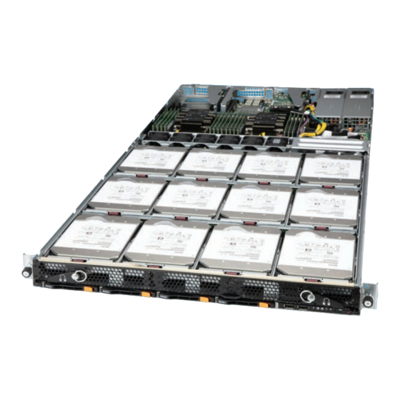
Chapter 1: Introduction Chapter 1 Introduction 1.1 Overview This chapter provides a brief outline of the functions and features of the SSG-6119P-ACR12N4L. The SSG-6119P-ACR12N4L is based on the X11DPD-M25 motherboard and the SC802TS-R0AMNDP chassis. In addition to the motherboard and chassis, several important parts that are included with the system are listed below. -
Page 10: System Features
SuperStorageServer SSG-6119P-ACR12N4L User's Manual 1.3 System Features The following table provides you with an overview of the main features of the SSG-6119P-ACR12N4L. Please refer to Appendix C for additional specifications. System Features Motherboard X11DPD-M25 Chassis SC802TS-R0AMNDP Intel® Xeon® Scalable SP and 2nd Gen Intel® Xeon® Scalable SP processors... -
Page 11: Server Chassis Features
Chapter 1: Introduction 1.4 Server Chassis Features Control Panel There are two buttons located on the front of the chassis: a power on/off button and a UID button. In addition there are five LEDs. The locations of these buttons and LEDs on the control panel are described below. -
Page 12: Front Features
SuperStorageServer SSG-6119P-ACR12N4L User's Manual Front Features The SC802TS-R0AMNDP is a 1U chassis See the illustration below for the features included on the front of the chassis. Figure 1-2. Front Chassis View Front Chassis Features Item Feature Description Control Panel Control panel (see previous page for details) -
Page 13: Chassis Rear
Chapter 1: Introduction Chassis Rear The illustration below shows the features included on the rear of the chassis. Power supply modules display status lights. Figure 1-4. Rear View Rear Chassis Features Item Feature Description Power Supply Module 800W power supply (redundant; two power modules) I/O Ports I/O ports (see Section 4.3 for details) Three PCI expansion slots for add-on cards (see Section 3.4 for... -
Page 14: Motherboard Layout
SuperStorageServer SSG-6119P-ACR12N4L User's Manual 1.5 Motherboard Layout Below is a layout of the X11DPD-M25 with jumper, connector and LED locations shown. See the table on the following page for descriptions. For detailed descriptions, pinout information and jumper settings, refer to Chapter 4. -
Page 15: Quick Reference Table
IPMI_LAN Dedicated IPMI LAN Port JAIOM PCIe 3.0 x16 Supermicro Advanced I/O Module (AIOM) Slot (supported by CPU1) Front Control Panel Header Chassis Intrusion Header (Note: Please connect a cable from the JL1 header to the chassis to receive an alert via IPMI.) - Page 16 SuperStorageServer SSG-6119P-ACR12N4L User's Manual Description Status UID LED Solid Blue: Unit Identified Onboard Power LED Solid Green: Power On (Activity LED) Blinking Green: SFP28 Port 0 (JSFP0) Active LED_L0 SFP28 Port 0 (JSFP0) Link/Activity LED (Link LED) Solid Green: 25G...
- Page 17 Chapter 1: Introduction UPI 10.4G/11.2G T/s UPI2 UPI1 UPI0 UPI2 UPI1 UPI0 CPU1 CPU2 SLOT9 SLOT5 SLOT6 PCI-E X16 G3 PCI-E X16 G3 PCI-E X8 G3 PCI-E X16 G3 PCI-E X16 G3 PCI-E X16 G3 Cable AIOM RMII/NCSI PCI-E X8 G3 Mellanox SFP28 MT27712...
-
Page 18: Chapter 2 Server Installation
SuperStorageServer SSG-6119P-ACR12N4L User's Manual Chapter 2 Server Installation 2.1 Overview This chapter provides advice and instructions for mounting your system in a server rack. If your system is not already fully integrated with processors, system memory etc., refer to Chapter 4 for details on installing those specific components. -
Page 19: Rack Precautions
Chapter 2: Server Installation Rack Precautions • Ensure that the leveling jacks on the bottom of the rack are extended to the floor so that the full weight of the rack rests on them. • In single rack installations, stabilizers should be attached to the rack. In multiple rack in- stallations, the racks should be coupled together. -
Page 20: Mechanical Loading
SuperStorageServer SSG-6119P-ACR12N4L User's Manual Mechanical Loading Equipment should be mounted into a rack so that a hazardous condition does not arise due to uneven mechanical loading. Circuit Overloading Consideration should be given to the connection of the equipment to the power supply circuitry and the effect that any possible overloading of circuits might have on overcurrent protection and power supply wiring. -
Page 21: Installing The Chassis
Chapter 2: Server Installation 2.3 Installing the Chassis This section provides information on installing the chassis into a rack unit with the rails provided. The Toolless Rail System The SC802 chassis uses a toolless rail system that does not need any hand tool to mount the rails and chassis into the server rack. - Page 22 SuperStorageServer SSG-6119P-ACR12N4L User's Manual Insert the top hook first, push it downwards to allow its hook to rest and engage the selected mounting hole. When the top hook is rested and engaged into place, push the bottom lock into the lower hole until it clicks and snaps into place Insert until bottom lock snaps into place.
- Page 23 Chapter 2: Server Installation Slide rail mounted equipment is not to be used as a shelf or a work space. The illustration below shows both the left and right rails mounted on a rack, ready to accept the server chassis. Right Rail Left Rail Figure 2-3.
-
Page 24: Sliding The Chassis Onto The Rack Rails
SuperStorageServer SSG-6119P-ACR12N4L User's Manual Sliding the Chassis onto the Rack Rails Installing the Chassis into a Rack 1. Align the chassis rails with the front of the rack rails. 2. Slide the chassis rails into the rack rails, letting it rest on to the inner rail lips, while keeping the pressure even on both sides. - Page 25 Chapter 2: Server Installation The chassis can then be secured to the rack by two thumb screws located on the left and right of the front side of the chassis. Figure 2-5. Securing the Chassis to the Rack Removing the Rails Removing a rail is basically just the reverse of the installation procedure.
-
Page 26: Chapter 3 Maintenance And Component Installation
SuperStorageServer SSG-6119P-ACR12N4L User's Manual Chapter 3 Maintenance and Component Installation This chapter provides instructions on installing and replacing main system components. To prevent compatibility issues, only use components that match the specifications and/or part numbers given. Installation or replacement of most components require that power first be removed from the system. -
Page 27: Accessing The System
Chapter 3: Maintenance and Component Installation 3.2 Accessing the System The system is fully accessible by loosening the two front thumbscrews and pulling out the drive drawer completely. Lever Loosen Thumbscrews Lever then pull out levers Pull Out Figure 3-1. Removing the Chassis Cover Removing a Chassis Cover 1. -
Page 28: Motherboard Components
CPU socket cap is in place and that none of the socket pins are bent; otherwise, contact your retailer immediately. • Refer to the Supermicro website for updates on CPU support. • Please follow the instructions given in the ESD Warning section on the first page of this chapter before handling, installing, or removing system components. -
Page 29: Overview Of The Processor Socket Assembly
Chapter 3: Maintenance and Component Installation Overview of the Processor Socket Assembly The processor socket assembly contains 1) Intel Xeon Scalable-SP or 2nd Generation Intel Xeon Scalable-SP processor, 2) the narrow processor clip, 3) the dust cover, and 4) the CPU socket. -
Page 30: Overview Of The Processor Heatsink Module (Phm)
SuperStorageServer SSG-6119P-ACR12N4L User's Manual Overview of the Processor Heatsink Module (PHM) The Processor Heatsink Module (PHM) contains 1) a heatsink, 2) a narrow processor clip, and 3) Intel Xeon Scalable-SP or 2nd Generation Intel Xeon Scalable-SP processor. 1. Heatsink 2. Narrow processor clip 3. -
Page 31: Attaching The Processor To The Narrow Processor Clip To Create The Processor Package Assembly
Chapter 3: Maintenance and Component Installation Attaching the Processor to the Narrow Processor Clip to Create the Processor Package Assembly To properly install the CPU into the narrow processor clip, please follow the steps below. 1. Locate pin 1 (notch A), which is the triangle located on the top of the narrow processor clip. -
Page 32: Attaching The Processor Package Assembly To The Heatsink To Form The Processor Heatsink Module (Phm)
SuperStorageServer SSG-6119P-ACR12N4L User's Manual Attaching the Processor Package Assembly to the Heatsink to Form the Processor Heatsink Module (PHM) After you have made a processor package assembly by following the instructions on the previous page, please follow the steps below to mount the processor package assembly onto the heatsink to create the Processor Heatsink Module (PHM). -
Page 33: Preparing The Cpu Socket For Installation
Chapter 3: Maintenance and Component Installation Preparing the CPU Socket for Installation This motherboard comes with the CPU socket pre-assembled in the factory. The CPU socket contains 1) a dust cover, 2) a socket bracket, 3) the CPU (P) socket, and 4) a back plate. These components are pre-installed on the motherboard before shipping. -
Page 34: Installing The Processor Heatsink Module (Phm)
SuperStorageServer SSG-6119P-ACR12N4L User's Manual Installing the Processor Heatsink Module (PHM) 1. Once you have assembled the processor heatsink module (PHM) by following the instructions listed on previsou pages, you are ready to install the processor heatsink module (PHM) into the CPU socket on the motherboard. To install the PHM into the CPU socket, follow the instructions below. -
Page 35: Removing The Processor Heatsink Module (Phm) From The Motherboard
Chapter 3: Maintenance and Component Installation Removing the Processor Heatsink Module (PHM) from the Motherboard Before removing the processor heatsink module (PHM), unplug power cord from the power outlet. 1. Using a T30 Torx-bit screwdriver, turn the screws on the PHM counterclockwise to loosen them from the socket, starting with screw marked #4 (in the sequence of 4, 3, 2, 2. -
Page 36: Memory Support
SuperStorageServer SSG-6119P-ACR12N4L User's Manual Memory Support The X11DPD-M25 supports up to 4TB of 3DS Load Reduced DIMM (3DS LRDIMM), Load Reduced DIMM (LRDIMM), 3DS Registered DIMM (3DS RDIMM), Registered DIMM (RDIMM), Non-Volatile DIMM (NV-DIMM) DDR4(288-pin) ECC 2933*/2666/2400/2133 MHz memory in 16 memory slots. -
Page 37: Ddr4 Memory Support For Intel Xeon Scalable-Sp Processors
Notes: 1. 2933 MHz memory support in two-DIMMs per-channel (2DPC) configuration can be achieved by using memory purchased from Supermicro. 2. Support for 2933 MHz memory is dependent on the CPU SKU. 3. 16Gb-based memory modules are supported by 2nd Gen... -
Page 38: Dimm Population Guidelines For Optimal Performance
SuperStorageServer SSG-6119P-ACR12N4L User's Manual DIMM Population Guidelines for Optimal Performance For optimal memory performance, follow the instructions listed in the tables below when populating memory modules. Key Parameters for DIMM Configuration Key Parameters for DIMM Configurations Parameters Possible Values Number of Channels... -
Page 39: Dimm Population Table
Chapter 3: Maintenance and Component Installation DIMM Population Table Note: Unbalanced memory configuration decreases memory performance and is not recommended for Supermicro motherboards. Memory Population Table for the Motherboard Using Intel Xeon Scalable-SP and 2nd Gen Intel Xeon Scalable-SP Processors... -
Page 40: Memory Rank Sparing Tables
SuperStorageServer SSG-6119P-ACR12N4L User's Manual Memory Rank Sparing Tables Dual Rank Memory Rank Sparing (16GB DIMM) Memory Population Total RAM Detected One Rank Configuration Two Rank Configuration A1+B1 16GB 16GB A1+B1+C1 24GB 24GB A1+B1+C1+D1 32GB 32GB A1+B1+C1+D1+E1 40GB 40GB A1+B1+C1+D1+E1+F1 49GB... -
Page 41: Dcpmm Memory Population Tables For 2Nd Gen Intel Xeon Scalable-Sp Processors
Chapter 3: Maintenance and Component Installation DCPMM Memory Population Tables for 2nd Gen Intel Xeon Scalable-SP Processors Note: Only 2nd Gen Intel Xeon Scalable-SP (82xx/62xx/52xx/4215 series) processors support DCPMM memory. Symmetric Population within 1 CPU Socket Modes P1-DIMMF1 P1-DIMME1 P1-DIMMD1 P1-DIMMD2 P1-DIMMA2 P1-DIMMA1... -
Page 42: Dimm Installation
SuperStorageServer SSG-6119P-ACR12N4L User's Manual DIMM Installation LED_L1 LED_L0 JSFP1 JSFP0 COM1 IPMI_LAN USB2/3 JUIDB1 (3.0) JRK1 1. Follow the instructions given in the USB0/1 LEDM1 JPL1 M.2-H_1 M.2-H_2 memory population guidelines listed in JWD1 CTRL the previous sections to install memory... -
Page 43: Pci Expansion Card Installation
Chapter 3: Maintenance and Component Installation PCI Expansion Card Installation The chassis supports two full height and one low profile PCIe expansion cards. Installing an Expansion Card 1. Power down the system as described in Section 3.1 and remove the rear cover. 2. -
Page 44: Sas Backplane Information
SuperStorageServer SSG-6119P-ACR12N4L User's Manual SAS Backplane Information The SSG-6119P-ACR12N4L comes with three backplanes for four 3.5" SATA3 or SAS3 HDD drives (BPN-SAS3-802A-2). These backplanes have their own two LED indicators for activity and status as shown in the figure and table below. -
Page 45: Motherboard Battery
Chapter 3: Maintenance and Component Installation Motherboard Battery The motherboard uses non-volatile memory to retain system information when system power is removed. This memory is powered by a lithium battery residing on the motherboard. Replacing the Battery Begin by removing power from the system as described in section 3.1. 1. -
Page 46: Chassis Components
SuperStorageServer SSG-6119P-ACR12N4L User's Manual 3.4 Chassis Components Storage Drives The SC802TS chassis supports 12 3.5" storage drives in toolless drive carriers to simplify their removal from the chassis. These carriers also help promote proper airflow. The drives rest on metal brackets that runs the full width of the chassis. They attach to the system by means of three small, horizontal backplanes that supports four 3.5"... - Page 47 Chapter 3: Maintenance and Component Installation Latch Pull handle 3.5" HDD Figure 3-7. Adding and Replacing 3.5" Hard Drives Replacing a 2.5" Hard Drive 1. There is no need to power down. 2. Locate and press the latch on the HDD you wish to remove from the chassis, then pull the handle out.
-
Page 48: Drive Carrier Indicators (2.5" Drives Only)
Blinking at 1 Hz Attention state—do not remove NVMe device (not supported in VMD mode) Note: Enterprise level hard disk drives are recommended for use in Supermicro chassis and servers. For information on recommended HDDs, visit the Supermicro website at https://www. -
Page 49: Checking The Temperature Of An Nvme Drive
Chapter 3: Maintenance and Component Installation Figure 3-9. IPMI Screenshot Replacing the Drive 1. Insert the replacement drive. 2. IPMI > Server Health > NVMe SSD 3. Select Device, Group and slot and click Insert. The drive Status LED indicator flashes red, then turns off. -
Page 50: System Fans
SuperStorageServer SSG-6119P-ACR12N4L User's Manual System Fans Six 4-cm counter-rotating fans provide cooling for the system. Replacing a System Fan 1. If necessary, open the top rear cover of the chassis while the system is running to locate the position of the failed fan. Do not run the server for an extended time with the cover off. -
Page 51: Checking The Server Air Flow
Some backplanes allow the overheat temperature to be set at 45, 50, or 55 degrees by changing a jumper setting. For more information, consult the backplane user manual at www. supermicro.com. (Click Support, then the Manuals link.) Responses If the server overheats: 1. -
Page 52: Power Supply
Failed power supplies should be replaced as soon as convenient. The power supply modules are hot-swappable, meaning they can be changed without powering down the system. New units can be ordered directly from Supermicro or authorized distributors. These power supplies are auto-switching capable. This feature enables them to automatically sense the input voltage and operate at a 100-120v or 180-240v as needed by the system. -
Page 53: Power Supply Leds
Chapter 3: Maintenance and Component Installation Power Supply LEDs On the rear of the power supply module, an LED displays the status. • Solid Green: When illuminated, indicates that the power supply is on. • Solid Amber: When illuminated, indicates the power supply is plugged in and turned off, or the system is off but in an abnormal state. -
Page 54: Power Connections
SuperStorageServer SSG-6119P-ACR12N4L User's Manual Chapter 4 Motherboard Connections This section describes the connections on the motherboard and provides pinout definitions. Note that depending on how the system is configured, not all connections are required. The LEDs on the motherboard are also described here. A serverboard layout indicating component locations may be found in Chapter 1. -
Page 55: Headers And Connectors
PWM Control AIOM Slot The Supermicro Advanced I/O Module (AIOM) PCIe 3.0 x16 slot (JAIOM) can be utilized to offer additional LAN ports, VPU, storage devices, etc. on the motherboard. Please visit the Supermicro website for all available module options. Also, please note that it is mandatory to unplug power cords prior to removing or installing an AIOM module card. - Page 56 SuperStorageServer SSG-6119P-ACR12N4L User's Manual Inlet Sensor Header This header (JSEN1) allows BMC to monitor thermal inlet temperature. A special module is required. Please contact Supermicro at www.supermicro.com to purchase the module for this header. Refer to the table below for pin definitions.
- Page 57 Chapter 4: Motherboard Connections PCIe/SATA Hybrid M.2 Sockets This motherboard has two PCIe/SATA hybrid M.2 sockets (M.2-H_1, M.2-H_2). M.2 was formerly known as Next Generation Form Factor (NGFF) and serves to replace mini PCIe. M.2 socket 1 (M.2-H_1) supports PCIe 3.0 x4 (32 Gb/s) SSD cards in the 2280 form factor only.
-
Page 58: Control Panel
SuperStorageServer SSG-6119P-ACR12N4L User's Manual Control Panel JF1 contains header pins for various control panel connections. See the figure below for the pin locations and definitions of the control panel buttons and LED indicators. All JF1 wires have been bundled into a single cable to simplify this connection. Make sure the red wire plugs into pin 1 as marked on the motherboard. - Page 59 Chapter 4: Motherboard Connections Reset Button/UID Button The Reset Button/UID Button connection is located on pins 3 and 4 of JF1. Attach it to a hardware reset switch on the computer case to reset the system or use JP4 to set the function of pin 3 of JF1.
- Page 60 SuperStorageServer SSG-6119P-ACR12N4L User's Manual NIC1/NIC2 (LAN1/LAN2) The NIC (Network Interface Controller) LED connection for LAN port 1 is located on pins 11 and 12 of JF1, and LAN port 2 is on pins 9 and 10. Attach the NIC LED cables here to display network activity.
-
Page 61: Ports
Chapter 4: Motherboard Connections 4.3 Ports Rear I/O Ports See the figure below for the locations and descriptions of the various I/O ports on the rear of the motherboard. Rear I/O Ports Description No. Description COM Port (micro USB to COM) SFP28 Port 0 Link/Activity LED (LED_L0) USB2 (USB 3.0) SFP28 Port 0 (JSFP0) -
Page 62: Dedicated Ipmi Lan Port
SuperStorageServer SSG-6119P-ACR12N4L User's Manual Universal Serial Bus (USB) Ports and Headers There are two USB 3.0 ports (USB2/3) located on the I/O back panel. The motherboard also has a front access USB 2.0 header that supports two USB connections (USB0/1). The onboard header can be used to provide front side USB access with a cable (not included). -
Page 63: Sfp28 Ports (Jsfp0/Jsfp1)
Note: UID can also be triggered via IPMI on the motherboard. For more information on IPMI, please refer to the IPMI User's Guide posted on our website at http://www.supermicro.com. UID Switch... -
Page 64: Jumpers
SuperStorageServer SSG-6119P-ACR12N4L User's Manual 4.4 Jumpers Explanation of Jumpers To modify the operation of the motherboard, jumpers are used to choose between optional settings. Jumpers create shorts between two pins to change the function associated with it. Pin 1 is identified with a square solder pad on the printed circuit board. See the motherboard layout page for jumper locations. - Page 65 Chapter 4: Motherboard Connections JF1 Pin 3 Function Selection Use JP4 to set the function of pin 3 of JF1. Set JP4 with pins 1 and 2 jumped to the Reset Button. Set JP4 with pins 2 and 3 jumped to the UID Button (for SC802 front panel board). Refer to the table below for jumper settings.
- Page 66 SuperStorageServer SSG-6119P-ACR12N4L User's Manual Watch Dog JWD1 controls the Watch Dog function. Watch Dog is a monitor that can reboot the system when a software application hangs. Jumping pins 1-2 will cause Watch Dog to reset the system if an application hangs. Jumping pins 2-3 will generate a non-maskable interrupt signal for the application that hangs.
-
Page 67: Led Indicators
Chapter 4: Motherboard Connections 4.5 LED Indicators IPMI LAN LEDs The dedicated IPMI LAN has two LED indicators. The amber LED on the right of the IPMI LAN port indicates activity, while the LED on the left indicates the speed of the connection. See the table below for more information. - Page 68 SuperStorageServer SSG-6119P-ACR12N4L User's Manual Onboard Power LED The Onboard Power LED is located at LE2 on the motherboard. When this LED is lit, it means that power is present on the motherboard. In suspend mode, this LED will blink on and off.
-
Page 69: Chapter 5 Software
USB/SATA DVD drive, or a USB flash drive, or the IPMI KVM console. 2. Retrieve the proper RST/RSTe driver. Go to the Supermicro web page for your motherboard and click on "Download the Latest Drivers and Utilities", select the proper driver, and copy it to a USB flash drive. - Page 70 SuperStorageServer SSG-6119P-ACR12N4L User's Manual 4. During Windows Setup, continue to the dialog where you select the drives on which to install Windows. If the disk you want to use is not listed, click on “Load driver” link at the bottom left corner.
-
Page 71: Driver Installation
The Supermicro website contains drivers and utilities for your system at https://www. supermicro.com/wdl/driver. Some of these must be installed, such as the chipset driver. After accessing the website, go into the CDR_Images (in the parent directory of the above link) and locate the ISO file for your motherboard. Download this file to to a USB flash drive or a DVD. -
Page 72: Superdoctor ® 5
5.3 SuperDoctor ® The Supermicro SuperDoctor 5 is a program that functions in a command-line or web-based interface for Windows and Linux operating systems. The program monitors such system health information as CPU temperature, system voltages, system power consumption, fan speed, and provides alerts via email or Simple Network Management Protocol (SNMP). -
Page 73: Chapter 6 Uefi Bios
Chapter 6: UEFI BIOS Chapter 6 UEFI BIOS 6.1 Introduction This chapter describes the AMIBIOS™ Setup utility for the X11DPD-L/-M25 motherboard. The BIOS is stored on a chip and can be easily upgraded using a flash program. Note: Due to periodic changes to the BIOS, some settings may have been added or deleted and might not yet be recorded in this manual. -
Page 74: Main Setup
SuperStorageServer SSG-6119P-ACR12N4L User's Manual 6.2 Main Setup When you first enter the BIOS Setup utility, you will see the Main setup screen. You can always return to the Main setup screen by selecting the Main tab on the top of the screen. - Page 75 Chapter 6: UEFI BIOS Memory Information Total Memory This feature displays the total size of memory available in the system.
-
Page 76: Advanced Setup Configurations
SuperStorageServer SSG-6119P-ACR12N4L User's Manual 6.3 Advanced Setup Configurations Use the arrow keys to select the Advanced submenu and press <Enter> to access the submenu items. Warning: Take caution when changing the Advanced settings. An incorrect value, an improper DRAM frequency, or an incorrect BIOS timing setting may cause the system to malfunction. - Page 77 Chapter 6: UEFI BIOS Bootup NumLock State Use this feature to set the Power-on state for the <Numlock> key. The options are On and Off. Wait For "F1" If Error Select Enabled to force the system to wait until the <F1> key is pressed if an error occurs. The options are Disabled and Enabled.
- Page 78 SuperStorageServer SSG-6119P-ACR12N4L User's Manual Power Button Function This feature controls how the system shuts down when the power button is pressed. Select 4 Seconds Override for the user to power off the system after pressing and holding the power button for four seconds or longer. Select Instant Off to instantly power off the system as soon as the user presses the power button.
- Page 79 Chapter 6: UEFI BIOS Cores Enabled Use this feature to enable or disable CPU cores in the processor specified by the user. Use the <+> key and the <-> key on the keyboard to set the desired number of CPU cores you want to enable in a processor.
- Page 80 SuperStorageServer SSG-6119P-ACR12N4L User's Manual DCU Streamer Prefetcher (Available when supported by the CPU) If this feature is set to Enable, the DCU (Data Cache Unit) streamer prefetcher will prefetch data streams from the cache memory to the DCU (Data Cache Unit) to speed up data accessing and processing to enhance CPU performance.
- Page 81 Chapter 6: UEFI BIOS Select Max Power Efficient to maximize power saving; however, system performance may be substantially impacted because limited power use decreases the processor frequency. The options are Maximum Performance, Performance, Balanced Performance, Balanced Power, and Power. CPU P State Control (Available when Power Technology is set to Custom) SpeedStep (P-States) EIST (Enhanced Intel SpeedStep Technology) allows the system to automatically adjust...
- Page 82 SuperStorageServer SSG-6119P-ACR12N4L User's Manual Hardware PM (Power Management) State Control (Available when Power Technology is set to Custom) Hardware P-States If this feature is set to Disable, hardware will choose a P-state setting for the system based on an OS request. If this feature is set to Native Mode, hardware will choose a P-state setting based on OS guidance.
- Page 83 Chapter 6: UEFI BIOS Chipset Configuration Warning: Setting the wrong values in the following features may cause the system to malfunc- tion. North Bridge This feature allows the user to configure the settings for the Intel North Bridge. Ultra Path Interconnect) UPI ( Configuration ...
- Page 84 SuperStorageServer SSG-6119P-ACR12N4L User's Manual IO Directory Cache (IODC) Select Enable for the IODC (I/O Directory Cache) to generate snoops instead of gen- erating memory lockups for remote IIO (InvIToM) and/or WCiLF (Cores). Select Auto for the IODC to generate snoops (instead of memory lockups) for WCiLF (Cores). The...
- Page 85 Chapter 6: UEFI BIOS Isoc Mode Select Enable to enable Isochronous support to meet QoS (Quality of Service) require- ments. This feature is especially important for Virtualization Technology. The options are Disable, Enable, and Auto. Memory Configuration Integrated Memory Controller (iMC) Enforce POR Select POR to enforce POR restrictions for DDR4 memory frequency and voltage pro- gramming.
- Page 86 SuperStorageServer SSG-6119P-ACR12N4L User's Manual tRWSR (Read to Write turnaround time for Same Rank) Relaxation Select Enable to use the same tRWSR DDR timing setting among all memory channels, and in which case, the worst case value among all channels will be used. Select Dis- able to use different values for the tRWSR DDR timing settings for different channels as trained.
- Page 87 Chapter 6: UEFI BIOS Page Policy Use this feature to set the page policy for onboard memory support. The options are Auto, Closed, and Adaptive. IMC Interleaving Use this feature to configure interleaving settings for the IMC (Integrated Memory Control- ler), which will improve memory performance.
- Page 88 SuperStorageServer SSG-6119P-ACR12N4L User's Manual Memory Rank Sparing Select Enable to support memory-rank sparing to optimize memory performance. The options are Disable and Enable. Note: This feature will not be available when memory mirror mode is set to Mirror Mode 1LM or an AEP device is plugged in.
- Page 89 Chapter 6: UEFI BIOS IIO Configuration IIO Configuration EV DFX (Device Function On-Hide) Features When this feature is set to Enable, the EV_DFX Lock Bits that are located in a proces- sor will always remain clear during electric tuning. The options are Disable and Enable. CPU1 Configuration ...
- Page 90 SuperStorageServer SSG-6119P-ACR12N4L User's Manual CPU1 SLOT9 PCI-E 3.0 X16 (Available when the device is detected by the system) Link Speed Use this feature to configure the link speed of a PCI-E port specified by the user. The options are Auto, Gen 1 (2.5 GT/s), Gen 2 (5 GT/s), and Gen 3 (8 GT/s).
- Page 91 Chapter 6: UEFI BIOS IOU2 (IIO PCIe Br3) Use this feature to configure the PCI-E Bifurcation setting for a PCI-E port specified by the user. The options are x4x4x4x4, x4x4x8, x8x4x4, x8x8, x16, and Auto. P2_NVMe1 (Available when the device is detected by the system) ...
- Page 92 SuperStorageServer SSG-6119P-ACR12N4L User's Manual The following information is displayed: • PCI-E Port Link Status • PCI-E Port Link Max • PCI-E Port Link Speed PCI-E Port Max (Maximum) Payload Size Select Auto for the system BIOS to automatically set the maximum payload value for a PCI-E device specified by to user for system performance enhancement.
- Page 93 Chapter 6: UEFI BIOS (Intel IO Acceleration Technology) IOAT Configuration Disable TPH (TLP Processing Hint) TPH is used for data-tagging with a destination ID and a few important attributes. It can send critical data to a particular cache without writing through to memory. Select No in this item for TLP Processing Hint support, which will allow a "TPL request"...
- Page 94 SuperStorageServer SSG-6119P-ACR12N4L User's Manual to improve virtualization efficiency by simplifying interrupt migration and lessening the need of physical interrupts. The options are Enable and Disable. Coherency Support (Non-Isoch) Select Enable for the Non-Isoch VT-d engine to pass through DMA (Direct Memory Access) to enhance system performance.
- Page 95 Chapter 6: UEFI BIOS *If the feature, Intel® VMD for Volume Management Device for PStack2, is set to Enable, the following features will become available for user's configuration: CPU1 SLOT6 PCI-E 3.0 X8 VMD (Available when the device is detected by the system) Select Enable to enable Intel Volume Management Device Technology support for the root port specified by the user.
- Page 96 SuperStorageServer SSG-6119P-ACR12N4L User's Manual Note: After you've enabled VMD support on a NMVe port, this port will be dedicated for VMD use only. To reactivate this port for NMVe use, please disable VMD support on the port. Hot Plug Capable (Available when the device is detected by the system)
- Page 97 Chapter 6: UEFI BIOS IIO-PCIE Express Global Options PCI-E Completion Timeout Disable Use this feature to select the PCI-E Completion Time-out settings. The options are Yes, No, and Per-Port. South Bridge The following South Bridge information is displayed: • USB Module Version •...
- Page 98 SuperStorageServer SSG-6119P-ACR12N4L User's Manual • ME Firmware Status #2 • Current State • Error Code PCH SATA Configuration When this submenu is selected, the AMI BIOS automatically detects the presence of the SATA devices that are supported by the Intel PCH chip and displays the following items: SATA Controller This item enables or disables the onboard SATA controller supported by the Intel PCH chip.
- Page 99 Chapter 6: UEFI BIOS Spin Up Device When this feature is set to Enable, the SATA device installed on the SATA port specified by the user will start a COMRESET initialization when an edge is detected from 0 to 1. The options are Disable and Enable.
- Page 100 SuperStorageServer SSG-6119P-ACR12N4L User's Manual sSATA Port 0 ~ sSATA Port 5 Hot Plug Select Enable to support Hot-plugging for the device installed on an sSATA port specified by the user which will allow the user to replace the device installed in the slot without shutting down the system.
- Page 101 Chapter 6: UEFI BIOS Maximum Read Request Select Auto for the system BIOS to automatically set the maximum size for a read request for a PCI-E device to enhance system performance. The options are Auto, 128 Bytes, 256 Bytes, 512 Bytes, 1024 Bytes, 2048 Bytes, and 4096 Bytes. MMCFG Base This feature determines how the lowest MMCFG (Memory-Mapped Configuration) base is assigned to onboard PCI devices.
- Page 102 SuperStorageServer SSG-6119P-ACR12N4L User's Manual Onboard Video Option ROM Use this feature to select the Onboard Video Option ROM type. The options are Disabled, Legacy, and EFI. Network Stack Configuration Network Stack Select Enabled to enable PXE (Preboot Execution Environment) or UEFI (Unified Extensible Firmware Interface) for network stack support.
- Page 103 Chapter 6: UEFI BIOS Super IO Configuration Super IO Configuration The following Super IO information will be displayed: • Super IO Chip AST2500 Serial Port 1 Configuration Serial Port 1 Configuration This submenu allows the user to configure settings of Serial Port 1. Serial Port 1 Select Enabled to enable Serial Port 1.
- Page 104 SuperStorageServer SSG-6119P-ACR12N4L User's Manual Serial Port Console Redirection COM1 Console Redirection Select Enabled to enable COM Port 1 for Console Redirection, which will allow a client machine to be connected to a host machine at a remote site for networking. The options are Disabled and Enabled.
- Page 105 Chapter 6: UEFI BIOS Stop Bits A stop bit indicates the end of a serial data packet. Select 1 Stop Bit for standard serial data communication. Select 2 Stop Bits if slower devices are used. The options are 1 and 2. Flow Control Use this feature to set the flow control for Console Redirection to prevent data loss caused by buffer overflow.
- Page 106 SuperStorageServer SSG-6119P-ACR12N4L User's Manual Console Redirection Select Enabled to use the SOL port for Console Redirection. The options are Disabled and Enabled. *If the feature above is set to Enabled, the following features will become available for user's configuration: Console Redirection Settings This feature allows the user to specify how the host computer will exchange data with the client computer, which is the remote computer used by the user.
- Page 107 Chapter 6: UEFI BIOS Flow Control Use this feature to set the flow control for Console Redirection to prevent data loss caused by buffer overflow. Send a "Stop" signal to stop sending data when the receiving buffer is full. Send a "Start" signal to start sending data when the receiving buffer is empty. The options are None and Hardware RTS/CTS.
- Page 108 SuperStorageServer SSG-6119P-ACR12N4L User's Manual Console Redirection Select Enabled to use a COM port selected by the user for EMS Console Redirection. The options are Disabled and Enabled. *If the feature above is set to Enabled, the following features will become available for user's configuration: Console Redirection Settings...
- Page 109 Chapter 6: UEFI BIOS NUMA (Available when the OS supports this feature) Select Enabled to enable Non-Uniform Memory Access support to enhance system performance. The options are Disabled and Enabled. WHEA Support Select Enabled to support the Windows Hardware Error Architecture (WHEA) platform and provide a common infrastructure for the system to handle hardware errors within the Windows OS environment to reduce system crashes and to enhance system recovery and health monitoring.
- Page 110 This feature cannot be enabled in the production platforms. The options are Disabled and Enabled. SMCI BIOS-Based TPM Provision Support (Please confirm the description.) Use this feature to enable the Supermicro TPM provision support. The options are Disabled and Enabled.
- Page 111 "IIO Configuration" in the "Chipset/North Bridge" submenu.) Note 2: For more information on TPM, please refer to the TPM manual at http://www. supermicro.com/manuals/other/TPM.pdf. HTTP BOOT Configuration Use this feature to configure HTTP Boot settings for your system.
- Page 112 SuperStorageServer SSG-6119P-ACR12N4L User's Manual Commit Changes and Exit Select this feature to keep the changes you have made and exit from the system. Discard Changes and Exit Select this feature to discard the changes you have made and exit from the system.
- Page 113 Chapter 6: UEFI BIOS • Select a specific DIMM that you want to view. • DIMMs on Socket 0x0000: • DIMMs on Socket 0x0001: DIMM ID This submenu allows the user to view and to perform an action on a DCPMM module specified by the user.
- Page 114 SuperStorageServer SSG-6119P-ACR12N4L User's Manual • Subsystem vendor ID • Subsystem device ID • Device locator • Subsystem revision ID • Interface format code • Manufacturing Info valid • Manufacturing date • Manufacturing location • Memory type • Memory bank label •...
- Page 115 Chapter 6: UEFI BIOS • Peak power budget [mW] • Avg (Average) power budget [mW] • Max average power budget [mW] • Package sparing capable • Package sparing enabled • Package spares available • Configuration status • SKU violation • ARS status •...
- Page 116 SuperStorageServer SSG-6119P-ACR12N4L User's Manual • Media temperature injections counter • Software triggers counter • Master passphrase enabled Monitor health Select this submenu to view the health status and thresholds of the DCPMM module specified by the user. • Sensor Type: This feature displays the type of health items that are being monitored.
- Page 117 Chapter 6: UEFI BIOS • Current firmware version: This feature displays the current firmware version. • Selected firmware version: This feature allows the user to select a new firmware version to use. • File: This feature allows the user to specify the file path in the root directory that contains the new firmware for firmware update.
- Page 118 SuperStorageServer SSG-6119P-ACR12N4L User's Manual Regions Current configuration Region ID When this submenu is selected, the following items will display: • Region ID: This feature displays the Region ID of the DCPMM module. • DIMM ID: This feature displays the DIMM ID of the DCPMM module.
- Page 119 Chapter 6: UEFI BIOS Persistent memory type: This feature allows the user to specify the type of DCPMM memory capacity to be cre- ated. The options are App Direct and App Direct Not interleaved. Namespace Label version: Use this feature to view and modify the namespace label version to initialize when creat- ing goals.
- Page 120 SuperStorageServer SSG-6119P-ACR12N4L User's Manual Save After configuring the settings for the namespace above, click on <Save> to save changes. Delete After configuring the settings for the namespace above, click on <delete> to delete the changes you've made on the namespace. Please note that all data contained in the namespace will be deleted as well when you press <delete>.
- Page 121 Chapter 6: UEFI BIOS Back to Namespaces Select this feature and press <Enter> to go back to the Namespaces submenu. Back to main menu Select this feature and press <Enter> to go back to the Intel(R) Optane(TM) DC Per- sistent Memory Configuration menu. Total capacity This feature allows the user to set the total DCPMM resource capacity allocated across all segments in the host server.
- Page 122 SuperStorageServer SSG-6119P-ACR12N4L User's Manual FW (Firmware) diagnostics Select Enabled for the firmware diagnostics test be performed on the DCPMM module. The options are Disabled and Enabled. Security diagnostics Select Enabled for the security diagnostics test be performed on the DCPMM module. The options are Disabled and Enabled.
- Page 123 Chapter 6: UEFI BIOS Driver Health This submenu displays the health status of the drivers and controllers as detected by the system.
-
Page 124: Event Logs
SuperStorageServer SSG-6119P-ACR12N4L User's Manual 6.4 Event Logs Use this feature to configure Event Log settings. Note: After you've made a change on a setting below, please be sure to reboot the system for the change to take effect. Change SMBIOS Event Log Settings ... - Page 125 Chapter 6: UEFI BIOS SMBIOS Event Log Standard Settings Log System Boot Event Select Enabled to log system boot events. The options are Enabled and Disabled. MECI (Multiple Event Count Increment) Enter the increment value for the multiple event counter. Enter a number between 1 to 255. This is a numeric value.
-
Page 126: Ipmi
SuperStorageServer SSG-6119P-ACR12N4L User's Manual 6.5 IPMI Use this feature to configure Intelligent Platform Management Interface (IPMI) settings. BMC Firmware Revision This feature indicates the IPMI firmware revision used in your system. IPMI STATUS (Baseboard Management Controller) This feature indicates the status of the IPMI firmware installed in your system. - Page 127 Chapter 6: UEFI BIOS When SEL is Full This feature allows the user to determine what the BIOS should do when the system event log is full. Select Erase Immediately to erase all events in the log when the system event log is full.
- Page 128 SuperStorageServer SSG-6119P-ACR12N4L User's Manual Gateway IP Address This feature displays the Gateway IP address for this computer. This should be in decimal and in dotted quad form (i.e., 192.168.10.253). VLAN (Available when Update IPMI LAN Configuration is set to Yes) This feature displays the status of VLAN support.
-
Page 129: Security
Chapter 6: UEFI BIOS 6.6 Security This menu allows the user to configure the following security settings for the system. Administrator Password Use this feature to set the administrator password which is required to enter the BIOS Setup utility. The length of the password should be from 3 characters to 20 characters long. User Password Use this feature to set the user password which is required to enter the BIOS setup utility. - Page 130 SuperStorageServer SSG-6119P-ACR12N4L User's Manual Secure Boot Select Enabled to use Secure Boot settings. The options are Disabled and Enabled. Secure Boot Mode Use this feature to select the desired secure boot mode for the system. The options are Standard and Custom.
- Page 131 Chapter 6: UEFI BIOS Restore DB defaults Select Yes to restore database variables to the manufacturer default settings. The op- tions are Yes and No. Secure Boot variable : Size/Key#s/Key Source Platform Key (PK) This feature allows the user to enter and configure a set of values to be used as platform firmware keys for the system.
-
Page 132: Boot
SuperStorageServer SSG-6119P-ACR12N4L User's Manual 6.7 Boot Use this feature to configure Boot Settings: Boot mode select Use this feature to select the type of devices from which the system will boot. The options are LEGACY, UEFI, and DUAL. The default setting is DUAL. - Page 133 Chapter 6: UEFI BIOS Add New Boot Option This feature allows the user to add a new boot option to the boot priority features for your system. Add Boot Option Use this item to specify the name for the new boot option. Path for Boot Option Use this feature to enter the path for the new boot option in the format fsx:\path\filename.efi.
-
Page 134: Save & Exit
SuperStorageServer SSG-6119P-ACR12N4L User's Manual 6.8 Save & Exit Select the Save & Exit tab from the BIOS setup screen to configure the settings below. Save Options Discard Changes and Exit Select this option to exit from the BIOS Setup utility without making any permanent changes to the system configuration and reboot the computer. - Page 135 Chapter 6: UEFI BIOS Default Options Restore Optimized Defaults To set this feature, select Restore Defaults from the Exit menu and press <Enter> to load manufacturer default settings which are intended for maximum system performance but not for maximum stability. Save as User Defaults To set this feature, select Save as User Defaults from the Exit menu and press <Enter>.
-
Page 136: Appendix A Standardized Warning Statements For Ac Systems
Supermicro's Technical Support department for assistance. Only certified technicians should attempt to install or configure components. Read this appendix in its entirety before installing or configuring components in the Supermicro chassis. These warnings may also be found on our website at http://www.supermicro.com/about/... - Page 137 Appendix A: Standardized Warning Statements Warnung WICHTIGE SICHERHEITSHINWEISE Dieses Warnsymbol bedeutet Gefahr. Sie befinden sich in einer Situation, die zu Verletzungen führen kann. Machen Sie sich vor der Arbeit mit Geräten mit den Gefahren elektrischer Schaltungen und den üblichen Verfahren zur Vorbeugung vor Unfällen vertraut. Suchen Sie mit der am Ende jeder Warnung angegebenen Anweisungsnummer nach der jeweiligen Übersetzung in den übersetzten Sicherheitshinweisen, die zusammen mit diesem Gerät ausgeliefert wurden.
- Page 138 SuperStorageServer SSG-6119P-ACR12N4L User's Manual . ٌ ا ك ً ف حالة و ٌ يك أى تتسبب ف اصابة جسذ ة ٌ هذا الزهز ع ٌ خطز !تحذ ز قبل أى تعول عىل أي هعذات،يك عىل علن بالوخاطز ال ا ٌجوة عي الذوائز...
- Page 139 Appendix A: Standardized Warning Statements Warnung Vor dem Anschließen des Systems an die Stromquelle die Installationsanweisungen lesen. ¡Advertencia! Lea las instrucciones de instalación antes de conectar el sistema a la red de alimentación. Attention Avant de brancher le système sur la source d'alimentation, consulter les directives d'installation. .יש...
- Page 140 SuperStorageServer SSG-6119P-ACR12N4L User's Manual Warnung Dieses Produkt ist darauf angewiesen, dass im Gebäude ein Kurzschluss- bzw. Überstromschutz installiert ist. Stellen Sie sicher, dass der Nennwert der Schutzvorrichtung nicht mehr als: 250 V, 20 A beträgt. ¡Advertencia! Este equipo utiliza el sistema de protección contra cortocircuitos (o sobrecorrientes) del edificio.
- Page 141 Appendix A: Standardized Warning Statements Power Disconnection Warning Warning! The system must be disconnected from all sources of power and the power cord removed from the power supply module(s) before accessing the chassis interior to install or remove system components. 電源切断の警告...
- Page 142 SuperStorageServer SSG-6119P-ACR12N4L User's Manual אזהרה מפני ניתוק חשמלי !אזהרה יש לנתק את המערכת מכל מקורות החשמל ויש להסיר את כבל החשמלי מהספק .לפני גישה לחלק הפנימי של המארז לצורך התקנת או הסרת רכיבים يجب فصم اننظاو من جميع مصادر انطاقت وإ ز انت سهك انكهرباء من وحدة امداد...
- Page 143 Appendix A: Standardized Warning Statements Attention Il est vivement recommandé de confier l'installation, le remplacement et la maintenance de ces équipements à des personnels qualifiés et expérimentés. !אזהרה .צוות מוסמך בלבד רשאי להתקין, להחליף את הציוד או לתת שירות עבור הציוד واملدربيه...
- Page 144 SuperStorageServer SSG-6119P-ACR12N4L User's Manual Warnung Diese Einheit ist zur Installation in Bereichen mit beschränktem Zutritt vorgesehen. Der Zutritt zu derartigen Bereichen ist nur mit einem Spezialwerkzeug, Schloss und Schlüssel oder einer sonstigen Sicherheitsvorkehrung möglich. ¡Advertencia! Esta unidad ha sido diseñada para instalación en áreas de acceso restringido. Sólo puede obtenerse acceso a una de estas áreas mediante la utilización de una herramienta especial,...
- Page 145 Appendix A: Standardized Warning Statements Battery Handling Warning! There is the danger of explosion if the battery is replaced incorrectly. Replace the battery only with the same or equivalent type recommended by the manufacturer. Dispose of used batteries according to the manufacturer's instructions 電池の取り扱い...
- Page 146 SuperStorageServer SSG-6119P-ACR12N4L User's Manual هناك خطر من انفجار يف حالة اسحبذال البطارية بطريقة غري صحيحة فعليل اسحبذال البطارية فقط بنفس النىع أو ما يعادلها مام أوصث به الرشمة املصنعة جخلص من البطاريات املسحعملة وفقا لحعليامت الرشمة الصانعة 경고! 배터리가 올바르게 교체되지 않으면 폭발의 위험이 있습니다. 기존 배터리와 동일하거나 제...
- Page 147 Appendix A: Standardized Warning Statements ¡Advertencia! Puede que esta unidad tenga más de una conexión para fuentes de alimentación. Para cortar por completo el suministro de energía, deben desconectarse todas las conexiones. Attention Cette unité peut avoir plus d'une connexion d'alimentation. Pour supprimer toute tension et tout courant électrique de l'unité, toutes les connexions d'alimentation doivent être débranchées.
- Page 148 SuperStorageServer SSG-6119P-ACR12N4L User's Manual Backplane Voltage Warning! Hazardous voltage or energy is present on the backplane when the system is operating. Use caution when servicing. バックプレーンの電圧 システムの稼働中は危険な電圧または電力が、 バックプレーン上にかかっています。 修理する際には注意く ださい。 警告 当系统正在进行时,背板上有很危险的电压或能量,进行维修时务必小心。 警告 當系統正在進行時,背板上有危險的電壓或能量,進行維修時務必小心。 Warnung Wenn das System in Betrieb ist, treten auf der Rückwandplatine gefährliche Spannungen oder Energien auf.
- Page 149 Appendix A: Standardized Warning Statements هناك خطز مه التيار الكهزبايئ أوالطاقة املىجىدة عىل اللىحة عندما يكىن النظام يعمل كه حذ ر ا عند خدمة هذا الجهاس 경고! 시스템이 동작 중일 때 후면판 (Backplane)에는 위험한 전압이나 에너지가 발생 합니다. 서비스 작업 시 주의하십시오. Waarschuwing Een gevaarlijke spanning of energie is aanwezig op de backplane wanneer het systeem in gebruik is.
- Page 150 SuperStorageServer SSG-6119P-ACR12N4L User's Manual תיאום חוקי החשמל הארצי !אזהרה .התקנת הציוד חייבת להיות תואמת לחוקי החשמל המקומיים והארציים تركيب املعدات الكهربائية يجب أن ميتثل للقىاويه املحلية والىطىية املتعلقة بالكهرباء 경고! 현 지역 및 국가의 전기 규정에 따라 장비를 설치해야 합니다.
- Page 151 Appendix A: Standardized Warning Statements Attention La mise au rebut ou le recyclage de ce produit sont généralement soumis à des lois et/ou directives de respect de l'environnement. Renseignez-vous auprès de l'organisme compétent. סילוק המוצר !אזהרה .סילוק סופי של מוצר זה חייב להיות בהתאם להנחיות וחוקי המדינה التخلص...
- Page 152 SuperStorageServer SSG-6119P-ACR12N4L User's Manual Warnung Gefährlich Bewegende Teile. Von den bewegenden Lüfterblätter fern halten. Die Lüfter drehen sich u. U. noch, wenn die Lüfterbaugruppe aus dem Chassis genommen wird. Halten Sie Finger, Schraubendreher und andere Gegenstände von den Öffnungen des Lüftergehäuses entfernt.
- Page 153 Verbindungskabeln, Stromkabeln und/oder Adapater, die Ihre örtlichen Sicherheitsstandards einhalten. Der Gebrauch von anderen Kabeln und Adapter können Fehlfunktionen oder Feuer verursachen. Die Richtlinien untersagen das Nutzen von UL oder CAS zertifizierten Kabeln (mit UL/CSA gekennzeichnet), an Geräten oder Produkten die nicht mit Supermicro gekennzeichnet sind.
- Page 154 .قيرح وأ لطع يف ببستي دق ىرخأ تالوحمو تالباك يأ مادختسا .ميلسلا سباقلاو لصوملا مجح لبق نم ةدمتعملا تالباكلا مادختسا تادعملاو ةيئابرهكلا ةزهجألل ةمالسلا نوناق رظحيUL وأCSA ( ةمالع لمحت يتلاوUL/CSA) لبق نم ةددحملاو ةينعملا تاجتنملا ريغ ىرخأ تادعم يأ عمSupermicro.
- Page 155 사항을 준수하여 제공되거나 지정된 연결 혹은 구매 케이블, 전원 케이블 및 AC 어댑터를 사용하십시오. 다른 케이블이나 어댑터를 사용하면 오작동이나 화재가 발생할 수 있습니다. 전기 용품 안전법은 UL 또는 CSA 인증 케이블 (코드에 UL / CSA가 표시된 케이블)을 Supermicro 가 지정한 제품 이외의 전기 장치에 사용하는 것을 금지합니다. Stroomkabel en AC-Adapter...
-
Page 156: Appendix B Uefi Bios Recovery
Warning: Do not upgrade the BIOS unless your system has a BIOS-related issue. Flashing the wrong BIOS can cause irreparable damage to the system. In no event shall Supermicro be liable for direct, indirect, special, incidental, or consequential damages arising from a BIOS update. -
Page 157: Recovering The Main Bios Block With A Usb Device
1. Please use a different machine to download the BIOS package for your motherboard or your system from the product page available on our website at www.supermicro.com. 2. Extract the BIOS package to a USB device and rename the BIOS ROM file [BIOSname#.###] that is included in the BIOS package to SUPER.ROM for BIOS... - Page 158 SuperStorageServer SSG-6119P-ACR12N4L User's Manual 5. After locating the SUPER.ROM file, the system will enter the BIOS Recovery menu as shown below. Note: At this point, you may decide if you want to start the BIOS recovery. If you decide to proceed with BIOS recovery, follow the procedures below.
- Page 159 Appendix B: UEFI BIOS Recovery 7. After the BIOS recovery process is complete, press any key to reboot the system. Note: It is recommended that you update your BIOS after BIOS recovery. Please refer to Chapter 3 for BIOS update instructions. 8.
- Page 160 SuperStorageServer SSG-6119P-ACR12N4L User's Manual 9. When the UEFI Shell prompt appears, type fs# to change the device directory path. Go to the directory that contains the BIOS package you extracted earlier in Step 2. Enter flash.nsh BIOSname#.### at the prompt to start the BIOS update process.
-
Page 161: Appendix C Configuring Vroc Raid Settings
RAID settings. The D.3 section describes the use of journaling drive for the RAID5 volume (parity based RAID). Note 1: Only use NVMe devices that have been validated by Supermicro. For the lat- est updates, please contact us or refer to our website at https://www.supermicro.com. - Page 162 SuperStorageServer SSG-6119P-ACR12N4L User's Manual 6. When the following screen displays, use the down arrow key to select Intel® VMD Technology and press <Enter> to enter the Intel® VMD Technology submenu. 7. When the Intel® VMD Technology submenu appears, it will display all the PCI slots that can be configured for VMD support on the screen.
- Page 163 Appendix C: Configuring VROC RAID Settings 13. Navigate to the Advanced tab. 14. Use the arrow keys to select Intel(R) Virtual RAID on CPU and press <Enter> to access the menu items. The following screen will appear showing that the feature "All Intel VMD Controllers"...
- Page 164 SuperStorageServer SSG-6119P-ACR12N4L User's Manual 15. Use the arrow keys to select All Intel VMD Controllers and press <Enter> to access the menu items. The following screen will appear. It allows the user to create RAID volumes and configure settings of NVMe devices as detected by the system.
-
Page 165: Configuring Raid Settings
Appendix C: Configuring VROC RAID Settings C.2 Configuring RAID Settings Follow the instructions stated in the D.1 section to access the All Intel VMD Controllers menu items, the following screen will appear. Please carefully follow the instructions listed in this section to configure RAID settings for your devices as desired. To Create a RAID Volume Use the arrow keys to select Create RAID Volume from the screen above and press <Enter>... - Page 166 SuperStorageServer SSG-6119P-ACR12N4L User's Manual To Enter a Name for the RAID Volume From the Create RAID Volume submenu as shown on the previous screen, use the arrow keys to select Name and press <Enter>, and the following screen will display.
- Page 167 Appendix C: Configuring VROC RAID Settings To Set the RAID Level for the RAID Volume From the Create RAID Volume submenu, select RAID Level and press <Enter>. The following screen will display. Use the arrow keys to select the desired RAID level for the RAID volume that you've created. The options are RAID0(Stripe), RAID1(Mirror), RAID5(Parity), and RAID10(RAID0+1).
- Page 168 SuperStorageServer SSG-6119P-ACR12N4L User's Manual Enabling RAID Spanned over VMD Controllers From the Create RAID Volume submenu, use the arrow keys to select Enter RAID spanned over VMD Controllers and press <Enter>. The following screen will display. Enter a desired setting for your RAID volume in the pop-up menu. The options are (not selected) and X (selected).
- Page 169 Appendix C: Configuring VROC RAID Settings To Select Disks for the RAID Volumes From the Create RAID Volume submenu, use the arrow keys to highlight Select Disk: and press <Enter>. The following screen will display. The options are (not selected) and X (selected). Set the features one by one to X to select the desired RAID disks for your RAID volumes.
- Page 170 SuperStorageServer SSG-6119P-ACR12N4L User's Manual To Set Strip Size for the RAID Volume From the Create RAID Volume submenu, use the arrow keys to select Strip Size: and press <Enter>. The following screen will display. From the pop-up menu as shown above, select the desired RAID strip size for your RAID volume and press <Enter>.
- Page 171 Appendix C: Configuring VROC RAID Settings To Set the Capacity (GB) for the RAID Volume From the Create RAID Volume submenu, use the arrow keys to select Capacity (GB): and press <Enter>. The following screen will display. Enter the desired RAID capacity (in GB) in the pop-up menu to set the capacity for your RAID volume.
- Page 172 SuperStorageServer SSG-6119P-ACR12N4L User's Manual To Create Volumes To finalize your RAID volume configuration, select Create Volume from the Create RAID Volume submenu as shown on the screen below. After selecting Create Volume, press <Enter>. The following screen will appear and...
- Page 173 Appendix C: Configuring VROC RAID Settings To Display RAID Volumes For detailed RAID volume information, use the arrow keys to select the desired RAID volume as shown below. To Display RAID VOLUME Information When the screen above appears, press <Enter>. The RAID VOLUME INFO menu will appear and display the detailed information about the RAID volume you've selected as shown below.
- Page 174 SuperStorageServer SSG-6119P-ACR12N4L User's Manual To Delete a RAID Volume On the RAID VOLUME INFO menu, use the arrow keys to select Delete and press <Enter> to delete the RAID volume you have selected. The following screen will appear to confirm if you want to delete the RAID Volume. Select...
- Page 175 Appendix C: Configuring VROC RAID Settings To Reset the RAID Volume to non-RAID On the RAID VOLUME INFO submenu shown on the bottom screen of page 173, select the desired NVMe device from the list of RAID Member Disks and press <Enter> as shown below. Select Reset to Non-RAID from the screen below and press <Enter>...
- Page 176 SuperStorageServer SSG-6119P-ACR12N4L User's Manual To Turn on the Disk Locator LED Follow the instructions stated in the D.1 section to access the All Intel VMD Controllers menu. When the following screen displays, select a non-RAID physical disk to turn on the disk locator LED to locate a selected device.
- Page 177 Appendix C: Configuring VROC RAID Settings To Mark a RAID Volume as Spare Follow the instructions stated in the D.1 section to access the All Intel VMD Controllers menu. When the following screen appears, select a desired NVMe device from the list of Non-RAID Physical Disks.
- Page 178 SuperStorageServer SSG-6119P-ACR12N4L User's Manual When the following screen appears, select Yes to confirm that you want the selected device to be used as a spare device. The options are Yes and No. Note: A spare disk is used for automatic RAID volume rebuilds when status of failed, missing, or at risk is detected on the array disk.
- Page 179 Appendix C: Configuring VROC RAID Settings To Mark a RAID Volume as a Journaling Drive Refer to the instructions stated in the D.1 section to access the All Intel VMD Controllers menu. When the following screen appears, select a desired NVMe device from the list of Non-RAID Physical Disks for use as a journaling drive.
- Page 180 SuperStorageServer SSG-6119P-ACR12N4L User's Manual When the following screen appears, select Yes to confirm that the selected device is to be used as a journaling drive. The options are Yes and No. Note: RAID Write Hole (RWH) is a condition associated with a power/drive-failure/crash while writing to a RAID5 volume.
-
Page 181: Use Of Journaling Drive
Appendix C: Configuring VROC RAID Settings C.3 Use of Journaling Drive The following section describes the use of a journaling drive for the RAID5 volume, which is a parity-based RAID. Step 1. Refer to the instructions stated in the D.1 section to access All Intel VMD Controllers menu items. - Page 182 SuperStorageServer SSG-6119P-ACR12N4L User's Manual RWH Policy Press <Enter> and the following screen will appear. If any device has been set as a journaling drive (see pages and 180), the options are Distributed PPL, Journaling Drive, and Disable. If no device has been set as a journaling drive, the options are Distributed PPL and Disable.
- Page 183 Appendix C: Configuring VROC RAID Settings Step 3. Set the feature, RWH Policy, to Journaling Drive. Press <Enter> and the RWH JD feature will become available as shown below. RWH JD Use the arrow keys to select RWH JD. Press <Enter> and the following screen will appear. The feature displays the information of journaling drive(s).
- Page 184 SuperStorageServer SSG-6119P-ACR12N4L User's Manual Step 4. Use the arrow keys and press <Enter> to select the desired journaling drive from the option list of RWH JD. Step 5. For the changes to take effect, use the arrow keys to select Change RWH settings and press <Enter>.
-
Page 185: Appendix D Configuring Iscsi Settings
Appendix D: Configuring iSCSI Settings Appendix D Configuring iSCSI Settings Internet small computer system interface (iSCSI) is a protocol that defines how block-level data transports between the iSCSI initiator and iSCSI target over an Internet protocol (IP) network. The iSCSI initiator (client/host) enables a connection to the iSCSI target and initiates I/O requests. - Page 186 SuperStorageServer SSG-6119P-ACR12N4L User's Manual Onboard LAN1 Option ROM Use the arrow keys to select Onboard LAN1 Option ROM and press <Enter>. The options are Disabled, Legacy, and EFI. Set this feature to EFI. Note: If Onboard LAN1 Option ROM is set to EFI, all features for onboard LAN op- tion ROM will be set to EFI by the EFI driver.
- Page 187 Appendix D: Configuring iSCSI Settings Ipv4 PXE Support/Ipv6 PXE Support To enable Ipv4/Ipv6 PXE boot support, use the arrow keys to select and set Ipv4 PXE Support/ Ipv6 PXE Support to Enabled. Note: Enable both Ipv4 PXE Support and Ipv6 PXE Support to have iSCSI settings available.
-
Page 188: Configuring Iscsi Settings
SuperStorageServer SSG-6119P-ACR12N4L User's Manual D.2 Configuring iSCSI Settings iSCSI Initiator Name Use this feature to enter the unique initiator name in iSCSI qualified name (IQN) format. Add an Attempt Use the arrow keys to select Add an Attempt. - Page 189 Appendix D: Configuring iSCSI Settings Press <Enter> and the following screen will appear. Use the arrow keys to select the desired media access control address (MAC address), network interface card (NIC) port. Press <Enter> and the following screen will appear. iSCSI Attempt Name This feature displays the iSCSI attempt name.
- Page 190 SuperStorageServer SSG-6119P-ACR12N4L User's Manual iSCSI Mode Use this feature to set the iSCSI mode. The options are Disabled, Enabled, and Enabled for MPIO. Multipath I/O (MPIO) is a feature that allows the system to route I/O through the available paths if the active path fails (be sure to have more than one physical path connected to the system).
- Page 191 Appendix D: Configuring iSCSI Settings Connection Retry Count The valid range is 0~16. Use this feature to enter the number of logon sessions allowed for the iSCSI initiator to restart with the iSCSI target if the first logon connection fails. Connection Establishing Timeout Use this feature to set the logon connection establishing timeout (in milliseconds).
- Page 192 SuperStorageServer SSG-6119P-ACR12N4L User's Manual OUI-format ISID This feature displays the default ISID in OUI format. The value (in six bytes) is derived from the MAC address of the NIC port that you selected earlier. Configure ISID Press <Enter> to configure the ISID. The default value is derived from the last three bytes of...
- Page 193 Appendix D: Configuring iSCSI Settings Enable DHCP Use this feature to disable/enable dynamic host configuration protocol (DHCP) server service for the iSCSI initiator. The options are Disabled and Enabled. Note: Set the feature, Enable DHCP, to Disabled if you would like to specify the iSCSI initiator IP address/subnet mask/gateway.
- Page 194 SuperStorageServer SSG-6119P-ACR12N4L User's Manual Initiator Subnet Mask (available when Enable DHCP is set to Disabled) Use this feature to enter the desired iSCSI initiator subnet mask. Gateway (available when Enable DHCP is set to Disabled) Use this feature to enter the desired iSCSI initiator gateway.
- Page 195 Appendix D: Configuring iSCSI Settings Get target info via DHCP (available when Enable DHCP is set to Enabled) Use this feature to disable/enable dynamic host configuration protocol (DHCP) server service for the iSCSI target. The options are Disabled and Enabled. Note 1: Set the feature, Get target info via DHCP, to Disabled if you would like to specify the iSCSI target name/IP address/boot LUN.
- Page 196 SuperStorageServer SSG-6119P-ACR12N4L User's Manual Target Address Use this feature to enter the desired iSCSI target IP address. Target Port This feature displays the iSCSI target port. Boot LUN Use this feature to enter the LUN ID of boot LUN.
- Page 197 Appendix D: Configuring iSCSI Settings Authentication Type Use this feature to set the authentication method. The options are CHAP and None. Note: Challenge handshake authentication protocol (CHAP) is a protocol used to verify the identity of the peer of a connection. CHAP Type (available when Authentication Type is set to CHAP) Use this feature to set the CHAP type.
- Page 198 SuperStorageServer SSG-6119P-ACR12N4L User's Manual CHAP Name (available when Authentication Type is set to CHAP) Use this feature to enter the CHAP name authenticated by the iSCSI target. CHAP Secret (available when Authentication Type is set to CHAP) Use this feature to enter the CHAP secret (12~16 characters) authenticated by the iSCSI...
- Page 199 Appendix D: Configuring iSCSI Settings CHAP Status This feature displays the CHAP status. Reverse CHAP Name (available when CHAP Type is set to Mutual) Use this feature to enter the CHAP name authenticated by the iSCSI initiator.
- Page 200 SuperStorageServer SSG-6119P-ACR12N4L User's Manual Reverse CHAP Secret (available when CHAP Type is set to Mutual) Use this feature to enter the CHAP secret (12~16 characters) authenticated by the iSCSI initiator. Reverse CHAP Status (available when CHAP Type is set to Mutual)
- Page 201 Appendix D: Configuring iSCSI Settings Save Changes Use the arrow keys to select Save Changes and press <Enter> to save settings shown on the screen. Note: For the changes to take effect, save settings and restart the system. Back to Previous Page Use the arrow keys to select Back to Previous Page and press <Enter>.
- Page 202 SuperStorageServer SSG-6119P-ACR12N4L User's Manual The user will be returned to the main screen of iSCSI Configuration as shown below. Delete Attempts Use the arrow keys to select Delete Attempts. Press <Enter> and the following screen will appear.
- Page 203 Appendix D: Configuring iSCSI Settings Attempt 1 Use the feature to disable/enable Attempt 1. The options are Disabled and Enabled. Attempt 2 Use the feature to disable/enable Attempt 2. The options are Disabled and Enabled.
- Page 204 SuperStorageServer SSG-6119P-ACR12N4L User's Manual Commit Changes and Exit Press <Enter> to save changes and return to the main screen of iSCSI Configuration. Discard Changes and Exit Press <Enter> to return to the main screen of iSCSI Configuration without any change.
- Page 205 Appendix D: Configuring iSCSI Settings Change Attempt Order Use the arrow keys to select Change Attempt Order. Press <Enter> and the following screen will appear.
- Page 206 SuperStorageServer SSG-6119P-ACR12N4L User's Manual Change Attempt Order This feature is to change the Attempt order. Use arrow keys to select the desired Attempt, then <+/-> keys to move up/down the selected Attempt. For instance, move up the selected Attempt by using <+> key. Move down the selected Attempt by using <-> key.
- Page 207 Appendix D: Configuring iSCSI Settings Discard Changes and Exit Press <Enter> to return to the main screen of iSCSI Configuration without any change.
-
Page 208: Appendix E System Specifications
SuperStorageServer SSG-6119P-ACR12N4L User's Manual Appendix E System Specifications Processor Support Dual Intel® Xeon® Scalable SP and 2nd Gen Intel® Xeon® Scalable SP processors Note: Please refer to the motherboard specifications pages on our website for updates to supported processors. Chipset... - Page 209 Appendix E: System Specifications Regulatory Compliance Electromagnetic Emissions: FCC Class A, EN 55032 Class A, EN 61000-3-2/3-3, CISPR 32 Class A Electromagnetic Immunity: EN 55024/CISPR 24, (EN 61000-4-2, EN 61000-4-3, EN 61000-4-4, EN 61000-4-5, EN 61000-4-6, EN 61000-4-8, EN 61000-4-11), CNS14336-1, CNS13438, GB4943.1-2011, GB9254-2008(Class A) and GB17625.1-2012 Safety: CSA/EN/IEC/UL 60950-1 Compliant, UL or CSA Listed (USA and Canada), CE Marking (Europe) Other: VCCI-CISPR 32 and AS/NZS CISPR 32 Environmental: Directive 2011/65/EU and Delegated Directive (EU) 2015/863 and Directive 2012/19/EU...
-
Page 210: Bsmi/Rohs
SuperStorageServer SSG-6119P-ACR12N4L User's Manual E.1 BSMI/RoHS 限用物質含有情況標示聲明書 Declaration of the Presence Condition of the Restricted Substances Marking 設備名稱: 伺服器 / Server Equipment name Type designation (Type) 型號(型式): 802-R8X11 (系列型號: 802-8、SSG-6119P-ACR12N4L ) Restricted substances and its chemical symbols 限用物質及其化學符號 六價鉻 多溴聯苯... - Page 211 Appendix E: System Specifications 警告使用者 : 此為甲類資訊技術設備,於居住環境中使用時,可能會造成射頻擾動,在此種情況下, 使用者會被要求採取某些適當的對策。 輸入額定: 100-240Vac ~, 50/60Hz, 10-5.5A (x2) *使用者不能任意拆除或替換內部配備 *報驗義務人之姓名或名稱:美超微電腦股份有限公司 *報驗義務人之地址:新北市中和區建一路 150 號 3 樓...
Need help?
Do you have a question about the SuperStorageServer SSG-6119P-ACR12N4L and is the answer not in the manual?
Questions and answers