Table of Contents
Advertisement
Quick Links
Advertisement
Table of Contents

Subscribe to Our Youtube Channel
Related Manuals for Solid State Logic SB 32.24


Summary of Contents for Solid State Logic SB 32.24
- Page 1 SB 32.24 and SB 16.12 Network I/O User Guide Revision: 1.5...
- Page 2 As research and development is a continual process, Solid State Logic reserves the right to change the features and specifications described herein without notice or obligation. Solid State Logic cannot be held responsible for any loss or damage arising directly or indirectly from any error or omission in this manual.
-
Page 3: Table Of Contents
SB 32.24 and SB 16.12 User Guide Table of Contents Introduction Ownership Overview Stagebox Ownership Key Features Input Ownership SB 32.24 Front Panel Individual Input Ownership SB 32.24 Rear Panel Console Routing and Input Ownership SB 16.12 Front Panel Gain Compensation SB 16.12 Rear Panel... -
Page 4: Introduction
2 AES/EBU inputs, 8 analogue line outputs and 2 AES/EBU outputs. Both SB 32.24 and SB 16.12 can be controlled remotely from SSL Live and System T consoles as well as from SSL’s Network I/O Controller app for PC. -
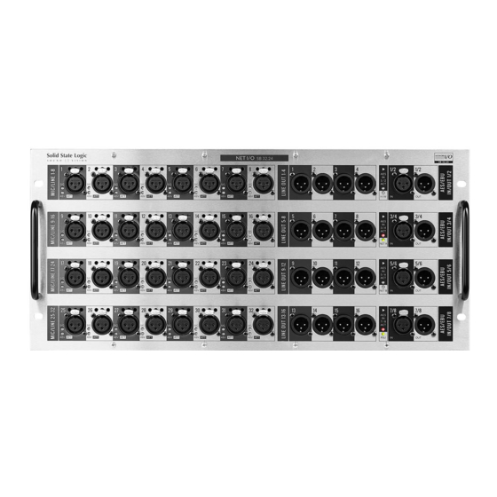
Page 5: Sb 32.24 Front Panel
SB 32.24 and SB 16.12 User Guide SB 32.24 Front Panel Signal Level and Latching XLR AES/Status 48V/Attention LEDs I/O Connectors LEDs SB 32.24 Rear Panel Network Redundant Network Redundant Low Noise Redundant Activity and Audio Connections Network B/ Fans... -
Page 6: Sb 16.12 Front Panel
SB 32.24 and SB 16.12 User Guide SB 16.12 Front Panel Latching XLR Signal Level and Four status LEDs provide hardware, Dante A, I/O Connectors 48V/Attention LEDs Dante B and PSU monitoring SB 16.12 Rear Panel Network Activity Redundant Network... -
Page 7: Status Leds
SB 32.24 and SB 16.12 User Guide Status LEDs A series of LEDs towards the right hand side of the front panel indicate statuses as follows. SB 32.24 H/W LED The AES IN ACT LEDs only apply to the SB 32.24, they Green - normal operation SB 16.12... -
Page 8: Device Reset
SB 32.24 and SB 16.12 User Guide Device Reset Performing a device reset will clear the SSL device settings. This includes ownership states and input settings. This does not clear Dante Brooklyn card settings. Brooklyn Reset Resetting the Dante Brooklyn card to default settings is performed from Dante Controller. Under the Device Config tab for a device select Clear Config. -
Page 9: Hardware Connections
GB/SFP shows Ethernet/SFP network status The SB 32.24 and SB 16.12 have two sets of redundant network connections. These can be configured in two different modes: In the first mode, the A and B networks are linked internally (A+B Network Link LED is on). In this mode both Network A and Network B are identical and output both the gain-dependant and gain- compensated audio. -
Page 10: Dante Connection Examples
I/O devices sending/receiving signals directly to/from the SB 32.24 or SB 16.12. Typically the master console will have control of the stagebox inputs. Additional consoles or I/O devices can subscribe to either the uncompensated or gain-compensated splits depending on the usage requirements and network link configuration. - Page 11 SB 32.24 and SB 16.12 User Guide Gain-Dependant Source and Gain-Compensated Splits Available to Two Consoles (SFPs Fitted) In this example, FOH and monitor consoles are Uncompensated both connected to the stagebox directly, using Gain Compensated Splits Main Audio (+Control) Network A (etherCON) and Network B (SFP) connections respectively.
-
Page 12: Network B Sample Rate Converter (Src)
SB 32.24 and SB 16.12 User Guide Network B Sample Rate Converter (SRC) A Sample Rate Converter (SRC) is available on the Network B Dante ports, allowing the gain compensated split outputs to run at a different sample rate or in a different clock domain to the main network. -
Page 13: Operation At Different Sample Rates
SB 32.24 running at 44.1 or 48 kHz. An SB 32.24 running at 88.2 or 96 kHz has a maximum of 32 inputs available. The last 8 inputs can either be analogue or AES. This is user-definable on a pair by pair basis directly from System T or Live console software, or using Network I/O Controller as shown in the AES I/O section of this guide. -
Page 14: Ssl Network I/O Controller
SB 32.24 and SB 16.12 User Guide SSL Network I/O Controller Installing Network I/O Controller When SSL Network I/O is used without an SSL console, configuration and control is achieved using the SSL Network I/O Controller PC application. This can be downloaded from the SSL website as part of the Network I/O Stagebox upgrade package or as a standalone installer. -
Page 15: Application Navigation
SB 32.24 and SB 16.12 User Guide Application Navigation Network I/O Controller is divided between three tabs: Control, Settings and Devices. These are accessed from the right hand side of the application. The Control view is the main application window, providing real- time control and monitoring of the connected SSL Network I/O devices. -
Page 16: Network View
SB 32.24 and SB 16.12 User Guide Network View A Red Highlight indicates a device that requires operator action: Device Name Selected device is highlighted • A flashing red background indicates a device with a clipping audio channel is set within with a cyan outline. -
Page 17: Inputs/Outputs
SB 32.24 and SB 16.12 User Guide Inputs/Outputs Select the Inputs, Outputs or AES I/O tab in the Page Select area to view I/O available on the network. Inputs Control Status shows whether the viewer has control of the input’s parameters. -
Page 18: Outputs
AES Input Enabled is only applicable to Take indicates that this input is NOT under the control of the viewer. Press and hold to take control from the the SB 32.24 and is detailed in the owner. Operation at Different Sample Rates Own indicates that this input is not owned by any controller. -
Page 19: Setup
SB 32.24 and SB 16.12 User Guide Setup Press Setup in the Page Select area to display the system configuration information. Stagebox Ownership and Inputs Ownership settings are detailed under Ownership. Info shows the status of the Operating Level allows selection Name shows the device device’s redundant power... -
Page 20: Devices View
SB 32.24 and SB 16.12 User Guide Devices View The Devices tab provides management of the I/O devices displayed in the Control View. Device Filtering allows Network I/O device types to be hidden, both from the Control View and the Control View Filtering and Sorting section. An example use case may be to hide all compensated devices so that the Control View only shows the gain tracked signals, not the compensated split feeds. -
Page 21: Ownership
Note that multiple consoles can share the same input signal but only one device can control the input parameters. Altering the input settings will affect all consoles using the input. N.B. Ownership settings are stored on the SB 32.24 and SB 16.12. The mute state is stored in... -
Page 22: Individual Input Ownership
SB 32.24 and SB 16.12 User Guide Individual Input Ownership One of three options will be displayed when an input is selected on a device, depending on the current ownership state. These options are Own, Take and Release: Inputs owned by another controller have a press and hold Take button. -
Page 23: Gain Compensation
When connected to an SSL console or the Network I/O Controller app the main and compensated channels show as two separate devices. The visibility of main and compensated channels for an SB 32.24 or SB 16.12 will depend on the network A and B link state, as detailed in Dante Connection Examples. -
Page 24: Calibration Point
SB 32.24 and SB 16.12 User Guide Calibration Point The Calibration point is the value at which the analogue gain equals a digital trim value of 0 dB, i.e. there is no digital trim applied. Digital trim will be applied when the analogue gain level is above or below the Calibration point. -
Page 25: Dante Controller
SB 32.24 and SB 16.12 User Guide Dante Controller Refer to Audinate’s Dante Controller user guide for complete information on Dante Controller software. The information below details the basics required to get started. Clock sync, device naming, AES67 configuration and network management are all done within Dante Controller. -
Page 26: Linking/Unlinking Networks A And B
SB 32.24 and SB 16.12 User Guide Linking/Unlinking Networks A and B The SB 32.24 and SB 16.12 can be configured to have both the gain-dependant and gain- compensated audio available on the same network, or to have them assigned to two separate (A/B) networks. -
Page 27: Appendix A - General Specifications
SB 32.24 and SB 16.12 User Guide Appendices Appendix A – General Specifications Parameter SB 32.24 SB 16.12 Notes 456 mm (18") 456 mm (18") (excluding handles) Depth 494 mm (19.5") 494 mm (19.5") (incl. handles) Height 220 mm (8.7") 133 mm (5.2”) -
Page 28: Appendix B - Connector Pin Outs
SB 32.24 and SB 16.12 User Guide Appendix B - Connector Pin Outs XLR Wiring Connector Dimensions: 19 x 60 mm (approx.) Cable Diameter: 8-12 mm (typical) Pinout for balanced audio: Pin 1 Screen/Ground Pin 2 Hot (+ve) Pin 3... -
Page 29: Appendix C - Performance Specifications
SB 32.24 and SB 16.12 User Guide Appendix C – Performance Specifications Mic/Line Inputs Parameter Value Notes Gain Range +26 to +70 dB Mic mode, 0 dBFS, 0.1 dB gain step size -4 to +30 dB Line mode, 0 dBFS, 0.1 dB gain step size... -
Page 30: Line Outputs
SB 32.24 and SB 16.12 User Guide Line Outputs Parameter Value Notes Maximum Output Level +24 dBu 600 Ω / 10 kΩ load Output Impedance < 50 Ω Frequency Response ± 0.3 dB -1 dBFS, 20 Hz – 20 kHz Usable Dynamic Range >... -
Page 31: Digital Inputs
SB 32.24 and SB 16.12 User Guide Digital Inputs Parameter Value Notes Input Impedance 110 Ω Transformer coupled Sample Rates 44.1, 48, 88.2 32 kHz - 216 kHz with sample rate converters or 96 kHz enabled Sample Rate converters Selectable per AES channel pair... -
Page 32: Appendix D - Safety Notices
SB 32.24 and SB 16.12 User Guide Appendix D – Safety Notices General Safety Please read and keep this document. Adhere to all warnings and follow instructions. This electrical equipment should not be used near water. Cleaning should only be with dry cloths or products compatible with electrical devices –... -
Page 33: Power Safety
SB 32.24 and SB 16.12 User Guide Power Safety The unit is not supplied with a mains lead allowing you to use IEC distribution of mains cables of your choice. Any mains cable used must fulfil the following: Refer to the ratings label on the rear of the unit and always use suitable mains cords. -
Page 34: Environmental Declaration
RoHS Notice Solid State Logic has conformed and this product has conformed to European Union’s Directive 2011/65/EU on Restrictions of Hazardous Substances (RoHS) as well as the following sections of California law which refer to RoHS, namely sections 25214.10, 25214.10.2, and 58012, Health and...
Need help?
Do you have a question about the SB 32.24 and is the answer not in the manual?
Questions and answers