Advertisement
Quick Links
Product Manual
Microprocessor-Based Generator Control Module
For Electronic J1939 CAN Bus Engines
Part Number: G3-1015
Revision: 2.3
______________________________________________________________________________________________________________________________________
Copyright Controls, Inc.
P.O. Box 368 • Sharon Center, OH 44274
Phone 330.239.4345 • Fax 330.239.2845 • www.controlsinc.com
Advertisement

Related Manuals for Controls G3-1015


Summary of Contents for Controls G3-1015
- Page 1 Product Manual Microprocessor-Based Generator Control Module For Electronic J1939 CAN Bus Engines Part Number: G3-1015 Revision: 2.3 ______________________________________________________________________________________________________________________________________ Copyright Controls, Inc. P.O. Box 368 • Sharon Center, OH 44274 Phone 330.239.4345 • Fax 330.239.2845 • www.controlsinc.com...
- Page 2 1.1 The G3-100 is a sealed microprocessor-based generator control system for electronic engines with J1939 CAN Bus. It is based on the Controls, Inc. uCAN series controller platform with a Freescale 8 bit processor. 1.2 The module is used for engine management and generator output display and is designed to be used with an XCAN-AC generator module.
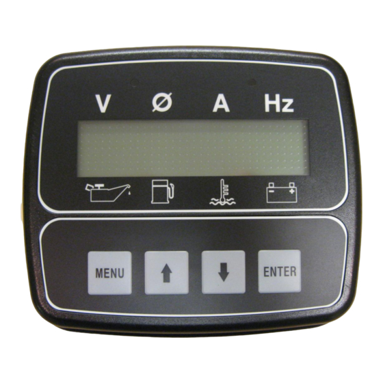
- Page 3 CONTROLS, INCORPORATED C O N T R O L S Y S T E M S & S O L U T I O N S 2) Interface 2.1 Display – The backlit digital display is 1”H x 4”W with two rows of 16 characters. Character height is approximately ½”.
- Page 4 CONTROLS, INCORPORATED C O N T R O L S Y S T E M S & S O L U T I O N S 3) Enclosure 3.1 ”uCAN” module is encased in a Sealed Polycarbonate Enclosure - 3 -...
-
Page 5: Part Number Breakdown
CONTROLS, INCORPORATED C O N T R O L S Y S T E M S & S O L U T I O N S 4) Complete Installation Kits Installation kits are available which include the following 1) Control panel, P/N G3-2500 (Includes the G3-100 Module) - Page 6 CONTROLS, INCORPORATED C O N T R O L S Y S T E M S & S O L U T I O N S 5) Panel Operation 5.1 The panel is designed to monitor the engine when the operator keys on or starts the engine.
- Page 7 CONTROLS, INCORPORATED C O N T R O L S Y S T E M S & S O L U T I O N S 5.1.3 Typical Operating Screen – The panel is synced up to the J1939 CAN Bus.
- Page 8 CONTROLS, INCORPORATED C O N T R O L S Y S T E M S & S O L U T I O N S 5.1.5 Controller monitored shutdowns – If configured the module can shut down the engine based on the engine parameters it is monitoring. Additionally, auxiliary inputs are available for analog fuel level monitoring and shutdown as well as a switch input for other shutdown switches.
- Page 9 CONTROLS, INCORPORATED C O N T R O L S Y S T E M S & S O L U T I O N S 5.1.6 Display Options – The controller can display all three phases at the same time by selecting the Gen Only screen option in the Module Configuration menu.
- Page 10 CONTROLS, INCORPORATED C O N T R O L S Y S T E M S & S O L U T I O N S 5.1.7 Throttle Operation – When operating throttle, a visual indication will be displayed to assure the operator the module is responding to the request.
-
Page 11: Controller Menus
CONTROLS, INCORPORATED C O N T R O L S Y S T E M S & S O L U T I O N S 6) 55) Controller Menus 5.1 The control panel a menus system to view various engine related information and set up the controller programming. - Page 12 CONTROLS, INCORPORATED C O N T R O L S Y S T E M S & S O L U T I O N S 5.4 Menu Access & Navigation 5.4.1 Accessing Menus 1. Press and hold the MENU key & simultaneously press the ENTER key.
- Page 13 CONTROLS, INCORPORATED C O N T R O L S Y S T E M S & S O L U T I O N S Entering into category Viewing logged events - 12 -...
- Page 14 CONTROLS, INCORPORATED C O N T R O L S Y S T E M S & S O L U T I O N S 5.4.3 Password Entry The password screen is provided to restrict the edit of sensitive values to authorized personnel.
- Page 15 CONTROLS, INCORPORATED C O N T R O L S Y S T E M S & S O L U T I O N S Leaving during editing will abandon the edit, and the old value will be retained.
-
Page 16: Input Configuration
CONTROLS, INCORPORATED C O N T R O L S Y S T E M S & S O L U T I O N S 7) Input Configuration Heading Default Range Units Your Settings Analog 1 Function None See Notes... -
Page 17: Output Configuration
CONTROLS, INCORPORATED C O N T R O L S Y S T E M S & S O L U T I O N S 8) Output Configuration Heading Default Range Units Your Settings Relay 1 Function Start Warn... - Page 18 CONTROLS, INCORPORATED C O N T R O L S Y S T E M S & S O L U T I O N S Low Oil Press Alarm – Relay closes if a low oil pressure shutdown is detected.
- Page 19 CONTROLS, INCORPORATED C O N T R O L S Y S T E M S & S O L U T I O N S 9) Throttle Configuration Heading Default Range Units Your Settings Throttle Type TSC Vern See Throttle Notes...
- Page 20 CONTROLS, INCORPORATED C O N T R O L S Y S T E M S & S O L U T I O N S 10) Engine Safety Configuration Heading Default Range Units Your Settings 0:05 – 1:00 Sender Check Bypass...
-
Page 21: Module Configuration
CONTROLS, INCORPORATED C O N T R O L S Y S T E M S & S O L U T I O N S 11) Module Configuration Heading Default Range Units Your Settings LCD Auto Contrast On / Off... - Page 22 CONTROLS, INCORPORATED C O N T R O L S Y S T E M S & S O L U T I O N S 13) Auto Start Configuration ( –AS Models Only) Heading Default Range Units Your Settings 0:00 –...
- Page 23 CONTROLS, INCORPORATED C O N T R O L S Y S T E M S & S O L U T I O N S 6) External Connectors 6.1 G3 Module Connector - The G3 module is connected to the internal wiring harness via a 14-pin TYCO plug.
- Page 24 CONTROLS, INCORPORATED C O N T R O L S Y S T E M S & S O L U T I O N S 9) DTC Codes (Diagnostic Trouble Codes). Note: If a DTC is not defined, the standard J1939 SPN.FMI format will be displayed.
- Page 25 CONTROLS, INCORPORATED C O N T R O L S Y S T E M S & S O L U T I O N S 44 DTC 1163: Adaptive-learn NG high 45 DTC 1164: Adaptive-learn NG low 46 DTC 261: Injector 1 open or short to ground...
- Page 26 CONTROLS, INCORPORATED C O N T R O L S Y S T E M S & S O L U T I O N S 93 DTC 628: Fuel-pump high-side open or short to ground 94 DTC 629: Fuel-pump high-side short to power...
- Page 27 CONTROLS, INCORPORATED C O N T R O L S Y S T E M S & S O L U T I O N S 142 DTC 1132: WGP voltage low 143 DTC 234: Boost control overboost failure 144 DTC 299: Boost control underboost failure...
- Page 28 CONTROLS, INCORPORATED C O N T R O L S Y S T E M S & S O L U T I O N S 191 DTC 1633: PWM2-Gauge2 open / ground short 192 DTC 1634: PWM2-Gauge2 short to power...
- Page 29 CONTROLS, INCORPORATED C O N T R O L S Y S T E M S & S O L U T I O N S 240 DTC 1426: ERWT2 higher than expected stage 2 241 DTC 8901: UEGO microprocessor internal fault...
- Page 30 CONTROLS, INCORPORATED C O N T R O L S Y S T E M S & S O L U T I O N S 289 Undefined DTC - Index 10289 290 Undefined DTC - Index 10290 291 Undefined DTC - Index 10291...
-
Page 31: Warranty
S O L U T I O N S 10) Warranty CONTROLS, INC. is herein called “Seller”. The person, firm or corporation to whom or which the sale is made is herein called “Buyer”. Seller warrants to the Buyer that all products furnished under this order will conform to Seller’s specification, drawings as described in its current catalog or quotation and will be...
Need help?
Do you have a question about the G3-1015 and is the answer not in the manual?
Questions and answers